STEERING COLUMN ASSEMBLY INSPECTION

Note
When using a vise, do not overtighten it.
-
INSPECT PRELOAD
-
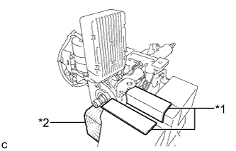
Text in Illustration *1 Aluminum Plate *2 Wooden Block Secure the steering column assembly in a vice using aluminum plates and wooden block as shown in the illustration.
Note
-
Do not overtighten the vice, as the steering column assembly may become deformed.
-
Support the steering column assembly with a wooden block or similar item to ensure that it does not fall.
-
-
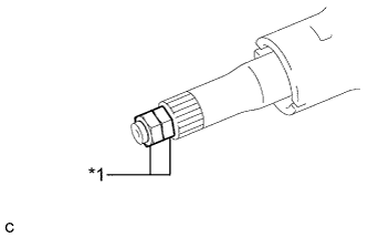
Text in Illustration *1 Service Nut Install the 2 service nuts to the steering main shaft.
Recommended service nut Thread diameter 12.0 mm (0.472 in.) Thread pitch 1.25 mm (0.0492 in.) -
Simultaneously rotate the service nut that was installed first counterclockwise and rotate the service nut that was installed second clockwise to lock them.
Note
Do not apply excess torque to the service nuts by using a tool such as an impact wrench.
Tech Tips
These nuts are installed to turn the steering main shaft. They should be removed after inspecting the steering main shaft rotating torque.
-
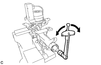
Using a torque wrench, turn the main shaft and measure the preload.
Preload 1.2 to 1.7 N*m (12 to 17 kgf*cm, 10 to 15 in.*lbf) If the preload is not as specified, replace the power steering motor assembly or electric power steering column sub-assembly with a new one.
-