PARKING BRAKE ASSEMBLY DISASSEMBLY

Note
-
When the brake pedal is first depressed after replacing the brake pads or pushing back the disc brake piston, DTC C1214 may be output. As there is no malfunction, clear the DTC.
-
While the auxiliary battery is connected, even if the power switch is off, the brake control system activates when the brake pedal is depressed or the door courtesy switch is turned on. Therefore, even if only brake pads are to be removed and installed, be sure to perform the Disable Brake Control procedure and disconnect the cable from the negative (-) terminal of the auxiliary battery before beginning work.
Tech Tips
-
Use the same procedure for the RH side and LH side.
-
The following procedure is for the LH side.
-
PRECAUTION
Note
After turning the power switch off, waiting time may be required before disconnecting the cable from the negative (-) auxiliary battery terminal, Therefore, make sure to read the disconnecting the cable from the negative (-) auxiliary battery terminal notice before proceeding with work Click here.
-
DISABLE BRAKE CONTROL
-
Wait at least 2 minutes after turning the power switch off.
Note
When the brake pedal is depressed or the door courtesy switch is turned on even if the power switch is off, the brake control system activates. Therefore do not depress the brake pedal or open/close the doors until the reservoir level switch connector is disconnected.
-
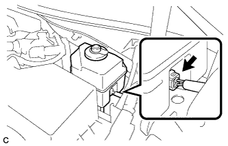
Disconnect the reservoir level switch connector with the parking brake applied.
-
Disconnect the cable from the negative (-) auxiliary battery terminal Click here.
-
Depress the brake pedal 40 times or more to return all the fluid in the accumulator back to the reservoir.
-
Check that the brake pedal can not be further depressed.
-
Release the parking brake.
-
-
REMOVE REAR WHEEL
-
SEPARATE REAR DISC BRAKE CALIPER ASSEMBLY
-
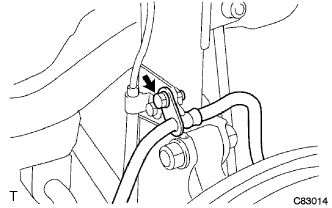
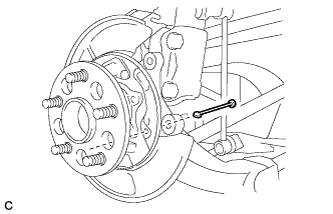
Remove the bolt and separate the rear flexible hose from the rear shock absorber.
-
Remove the 2 bolts, and separate the rear disc brake caliper assembly.
Note
Use wire or an equivalent tool to keep the rear disc brake caliper from hanging down by the flexible hose.
-
-
REMOVE PARKING BRAKE SHOE ADJUSTING HOLE PLUG
-
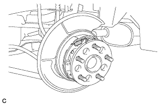
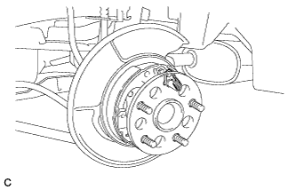
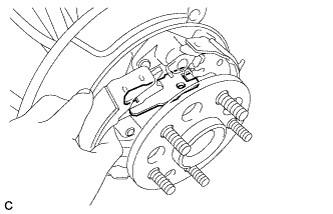
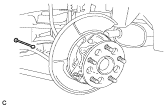
REMOVE REAR DISC
-
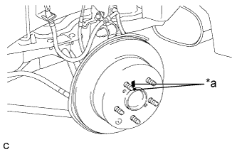
Text in Illustration *a Matchmark Put matchmarks on the rear disc and the rear axle hub.
-
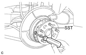
Release the parking brake and remove the rear disc.
Tech Tips
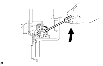
If the disc cannot be removed easily, use a screwdriver to turn the shoe adjuster as shown in the illustration in order to contract the parking brake shoes.
-
-
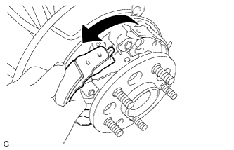
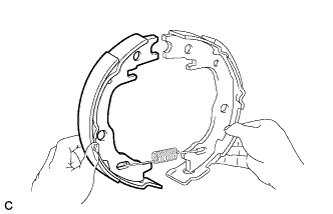
REMOVE PARKING BRAKE SHOE RETURN TENSION SPRING (for Front Side)
-
Remove the parking brake shoe return tension spring.
-
-
REMOVE PARKING BRAKE SHOE RETURN TENSION SPRING (for Rear Side)
-
Remove the parking brake shoe return tension spring.
-
-
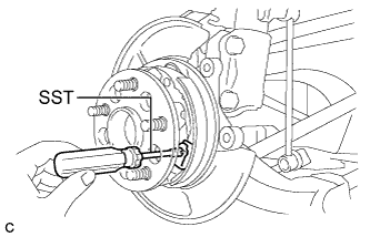
REMOVE PARKING BRAKE SHOE HOLD DOWN COMPRESSION SPRING (for Front Side)
-
Using SST, remove the parking brake shoe hold down compression spring.
- SST
- 09718-00011
-
-
REMOVE PARKING BRAKE SHOE STRUT
-
Pull the No. 1 parking brake shoe assembly towards the front of the vehicle by hand as shown in the illustration.
-
Remove the parking brake shoe strut.
-
-
REMOVE PARKING BRAKE SHOE HOLD DOWN COMPRESSION SPRING (for Rear Side)
-
Using SST, remove the parking brake shoe hold down compression spring.
- SST
- 09718-00011
-
-
SEPARATE PARKING BRAKE SHOE LEVER
-
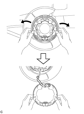
Expand the No. 1 and No. 2 parking brake shoe assemblies outward by hand and pull downward to separate them from the parking brake plate.
-
Separate the parking brake shoe lever from the No. 2 parking brake shoe assembly.
-
-
REMOVE PARKING BRAKE SHOE ADJUSTING SCREW SET
-
Remove the parking brake shoe adjusting screw set.
-
-
REMOVE NO. 1 PARKING BRAKE SHOE ASSEMBLY
-
Remove the No. 1 parking brake shoe assembly.
-
-
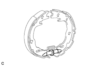
REMOVE PARKING BRAKE SHOE RETURN TENSION SPRING (for Lower Side)
-
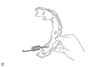
Remove the parking brake shoe return tension spring.
-
-
REMOVE PARKING BRAKE SHOE LEVER
-
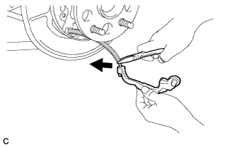
Using needle-nose pliers, remove the parking brake shoe lever from the No. 3 parking brake cable assembly as shown in the illustration.
-
-
REMOVE PARKING BRAKE SHOE HOLD DOWN SPRING PIN
-
Remove the parking brake shoe hold down spring pin (for front side).
-
Remove the parking brake shoe hold down spring pin (for rear side).
-