PARKING BRAKE PEDAL INSTALLATION

-
INSTALL PARKING BRAKE CONTROL PEDAL ASSEMBLY
-
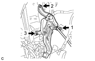
Install the parking brake control pedal assembly with the bolt and 2 nuts.
- Torque:
- 15 N*m { 153 kgf*cm, 11 ft.*lbf }
Note
Tighten the bolt and 2 nuts in the order shown in the illustration.
-
Connect the parking brake switch connector.
-
Install the No. 1 parking brake cable assembly with the bolt and 2 nuts.
- Torque:
- Bolt
- 15 N*m { 153 kgf*cm, 11 ft.*lbf }
- Nut
- 5.4 N*m { 55 kgf*cm, 48 in.*lbf }
-
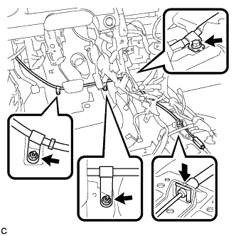
Install the clip to the No. 1 parking brake cable assembly.
-
Install the floor carpet.
-
-
CONNECT NO. 4 PARKING BRAKE CABLE ASSEMBLY
-
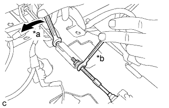
Text in Illustration *a Turn *b Hold Connect the No. 4 parking brake cable assembly to the parking brake control pedal assembly as shown in the illustration.
- Torque:
- 5.4 N*m { 55 kgf*cm, 48 in.*lbf }
-
-
INSTALL POWER MANAGEMENT CONTROL ECU
-
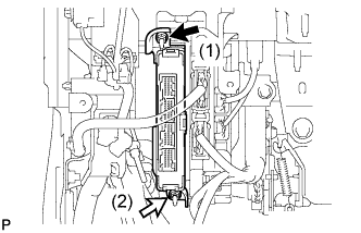
Install the power management control ECU with the 2 nuts in the order shown in the illustration.
- Torque:
- 7.5 N*m { 76 kgf*cm, 66 in.*lbf }
-
Connect the 4 connectors.
-
-
INSTALL AIRBAG SENSOR ASSEMBLY
-
Check that the power switch is off.
-
Check that the cable is disconnected from the negative (-) auxiliary battery terminal.
CAUTION:
Wait at least 90 seconds after disconnecting the cable from the negative (-) auxiliary battery terminal to disable the SRS system.
-
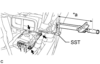
Text in Illustration *a Fulcrum Length Using SST, install the airbag sensor assembly with the 3 bolts.
- SST
- 09961-00950
- Torque:
- without SST
- 18 N*m { 178 kgf*cm, 13 ft.*lbf }
- with SST
- 11 N*m { 112 kgf*cm, 8 ft.*lbf }
Note
-
Use a torque wrench with a fulcrum length of 250 mm (9.84 in.).
-
This torque value is effective when SST is parallel to a torque wrench.
-
If the airbag sensor assembly has been dropped, or there are any cracks, dents or other defects in the case or connector, replace it with a new one.
-
When installing the airbag sensor assembly, be careful that the SRS wiring does not interfere with or is not pinched between other parts.
-
When the power switch is first turned on (IG) after the airbag sensor assembly has been replaced, make sure that no one is in the vehicle.
-
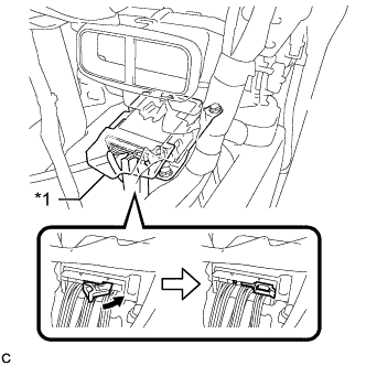
Text in Illustration *1 Waterproof Sheet Connect the connectors to the airbag sensor assembly as shown in the illustration.
Note
When connecting any airbag connector, take care not to damage the airbag wire harness.
-
Check that the waterproof sheet is properly set.
-
Check that there is no looseness in the installation parts of the airbag sensor assembly.
-
-
INSTALL FLOOR CARPET BRACKET RH
-
Engage the 2 guides.
-
Install the floor carpet bracket RH with the 2 clips.
-
-
INSTALL NO. 1 INDOOR ELECTRICAL KEY ANTENNA ASSEMBLY
-
Connect the connector.
-
Install the No. 1 indoor electrical key antenna assembly with the bolt.
Note
Be careful when installing the indoor electrical key antenna assembly. If the antenna is dropped, replace it with a new one.
-
Engage the clamp.
-
-
INSTALL LOWER NO. 1 INSTRUMENT PANEL AIRBAG ASSEMBLY
-
Check that the power switch is off.
-
Check that the cable is disconnected from the negative (-) auxiliary battery terminal.
CAUTION:
Wait at least 90 seconds after disconnecting the cable from the negative (-) auxiliary battery terminal to disable the SRS system.
-
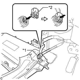
Text in Illustration *1 Airbag Connector *2 Airbag Connector Lock Connect the airbag connector to the lower No. 1 instrument panel airbag assembly.
Note
When connecting any airbag connector, take care not to damage the airbag wire harness.
-
Push in the lock to install the airbag connector.
-
Temporarily install the lower No. 1 instrument panel airbag assembly with the 2 hooks.
-
Engage the 2 claws to install the DLC3.
-
Install the 4 bolts.
- Torque:
- 10 N*m { 102 kgf*cm, 7 ft.*lbf }
Note
Confirm that the lower No. 1 instrument panel airbag assembly is installed securely without any excessive gaps and is not protruding outward.
-
-
INSTALL SHIFT LEVER SUPPORT
-
CONNECT CABLE TO AUXILIARY BATTERY NEGATIVE TERMINAL
Note
When disconnecting the cable, some systems need to be initialized after the cable is reconnected Click here.
-
INSTALL LUGGAGE TRIM SERVICE HOLE COVER
-
Engage the claw to connect the luggage trim service hole cover.
-
-
PERFORM DIAGNOSTIC SYSTEM CHECK
-
INSPECT SRS WARNING LIGHT
-
ADJUST PARKING BRAKE PEDAL TRAVEL
-
Completely release the parking brake pedal.
-
Remove the lower No. 1 instrument panel finish panel assembly Click here.
-
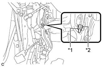
Text in Illustration *1 Lock Nut *2 Adjusting Nut Remove the lock nut and loosen the adjusting nut to completely release the parking brake cable.
Note
If the lock nut is removed or loosened, replace the lock nut with a new one.
-
Remove the rear wheels.
-
Temporarily install the hub nuts to the hub bolts.
Tech Tips
Securely install the hub nuts to the rear disc.
-
Remove the parking brake shoe adjusting hole plug.
-
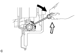
Turn the shoe adjuster and expand the shoes until the disc locks.
Text in Illustration 
Expand 
Contract -
Turn and contract the shoe adjuster until the disc can rotate smoothly.
Standard Returns 8 notches. -
Check that there is no brake drag against the shoe.
-
Install the parking brake shoe adjusting hole plug.
-
Turn the adjusting nut until the parking brake pedal travel is corrected to be within the specified range.
Parking brake pedal travel 7 to 10 notches at 300 N (31 kgf, 67.5 lbf) -
Using a wrench or an equivalent tool, hold the adjusting nut and install a new lock nut.
- Torque:
- 5.0 N*m { 51 kgf*cm, 44 in.*lbf }
-
Operate the parking brake pedal 3 to 4 times, and check the parking brake pedal travel.
-
Check that the parking brake does not drag.
-
Install the lower No. 1 instrument panel finish panel assembly Click here.
-
Remove the hub nuts from the hub bolts.
-
Install the rear wheels.
- Torque:
- 103 N*m { 1049 kgf*cm, 76 ft.*lbf }
-
-
INSPECT BRAKE WARNING LIGHT
-
When operating the parking brake pedal, check that the brake warning light illuminates.
Standard The brake warning light always illuminates at the first click.
-