ELECTRONICALLY CONTROLLED BRAKE SYSTEM TRAC OFF Indicator Light Remains ON
DESCRIPTION
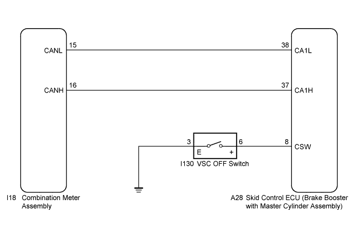
The skid control ECU (brake booster with master cylinder assembly) is connected to the combination meter assembly via CAN communication.
Pressing the VSC OFF switch turns off traction control and pressing and holding this switch turns off traction and VSC controls. If TR(A)C control is turned off, the TR(A)C OFF indicator light will come on.
WIRING DIAGRAM
INSPECTION PROCEDURE
Note
When replacing the skid control ECU (brake booster with master cylinder assembly), perform initialization and calibration of the linear solenoid valve Click here.
PROCEDURE
-
CHECK CAN COMMUNICATION SYSTEM
-
Check if CAN communication system DTCs are output Click here.
Result Result Proceed to DTC is not output. A DTC is output. B
B 
INSPECT CAN COMMUNICATION SYSTEM Click here
A 
-
-
CHECK IF SKID CONTROL ECU CONNECTOR IS SECURELY CONNECTED
-
Check if the skid control ECU (brake booster with master cylinder assembly) connector is securely connected.
OK The connector is securely connected.
NG
CONNECT CONNECTOR TO ECU CORRECTLY
OK
-
-
CHECK AUXILIARY BATTERY
-
Check the auxiliary battery voltage.
Standard Voltage Tester Connection Condition Specified Condition Auxiliary battery Power switch on (IG) 11 to 14 V Auxiliary battery Power switch on (READY) 11 to 15.5 V
NG
CHARGE OR REPLACE AUXILIARY BATTERY
OK
-
-
READ VALUE USING TECHSTREAM (VSC OFF SWITCH)
-
Connect the Techstream to the DLC3.
-
Turn the power switch on (IG).
-
Select the Data List on the Techstream Click here.
ABS/VSC/TRAC Tester Display Measurement Item/Range Normal Condition Diagnostic Note TRAC/VSC Off Mode VSC OFF switch / Normal, TRC OFF, Unknown or VSC OFF Normal: Normal mode
TRC OFF: TR(A)C off mode
Unknown: Unspecified
VSC OFF: VSC off mode
- -
Using the Techstream, check that the switch condition on the Techstream changes according to VSC OFF switch operation.
NG 
INSPECT VSC OFF SWITCH Click here
OK
-
-
INSPECT COMBINATION METER ASSEMBLY
-
Turn the power switch off.
-
Perform the Active Test of the combination meter assembly (meter CPU) using the Techstream Click here.
-
Check the combination meter assembly.
OK The TR(A)C OFF indicator light turns on or off in accordance with Techstream operation. Tech Tips
If troubleshooting has been carried out according to Problem Symptoms Table, refer back to the table and proceed to the next step before replacing the part Click here.
NG
REPLACE COMBINATION METER ASSEMBLY Click here
OK 
REPLACE BRAKE BOOSTER WITH MASTER CYLINDER ASSEMBLY Click here
-
-
INSPECT VSC OFF SWITCH
-
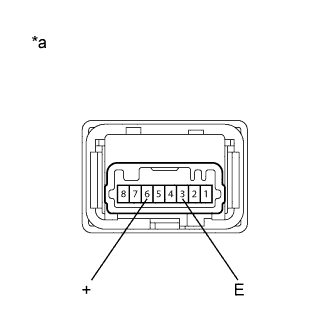
Text in Illustration *a Component without harness connected
(VSC OFF Switch)
Turn the power switch off.
-
Disconnect the VSC OFF switch connector.
-
Measure the resistance according to the value(s) in the table below.
Standard Resistance Tester Connection Switch Condition Specified Condition 6 (+) - 3 (E) Switch is pushed in Below 1 Ω 6 (+) - 3 (E) Switch is not pushed in 10 kΩ or higher
NG
REPLACE VSC OFF SWITCH Click here
OK
-
-
CHECK HARNESS AND CONNECTOR (SKID CONTROL ECU - VSC OFF SWITCH)
-
Disconnect the skid control ECU (brake booster with master cylinder assembly) connector.
-
Measure the resistance according to the value(s) in the table below.
Standard Resistance Tester Connection Condition Specified Condition A28-8 (CSW) - I130-6 (+) Always Below 1 Ω A28-8 (CSW) - Body ground Always 10 kΩ or higher I130-3 (E) - Body ground Always Below 1 Ω Tech Tips
If troubleshooting has been carried out according to Problem Symptoms Table, refer back to the table and proceed to the next step Click here.
NG
REPAIR OR REPLACE HARNESS OR CONNECTOR
OK
REPLACE BRAKE BOOSTER WITH MASTER CYLINDER ASSEMBLY Click here
-