SHIFT LEVER REMOVAL

-
PRECAUTION
CAUTION:
Be sure to read Precaution thoroughly before servicing Click here.
Note
After turning the power switch off, waiting time may be required before disconnecting the cable from the auxiliary battery negative (-) terminal. Therefore, make sure to read the disconnecting the cable from the auxiliary battery negative (-) terminal notices before proceeding with work Click here.
-
REMOVE LUGGAGE TRIM SERVICE HOLE COVER
-
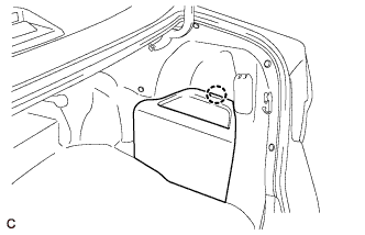
Disengage the claw to remove the luggage trim service hole cover.
-
-
DISCONNECT CABLE FROM AUXILIARY BATTERY NEGATIVE TERMINAL
CAUTION:
Wait at least 90 seconds after disconnecting the cable from the negative (-) auxiliary battery terminal to disable the SRS system.
Note
When disconnecting the cable, some systems need to be initialized after the cable is reconnected Click here.
-
REMOVE REAR CONSOLE BOX ASSEMBLY
-
REMOVE FRONT DOOR SCUFF PLATE LH
-
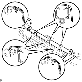
Disengage the 10 claws and remove the front door scuff plate LH.
-
-
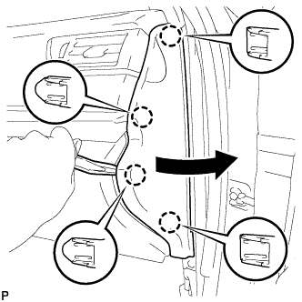
REMOVE COWL SIDE TRIM SUB-ASSEMBLY LH
-
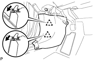
Remove the clip.
-
Pull the cowl side trim sub-assembly LH in the direction indicated by the arrow shown in the illustration to disengage the 2 clips and remove the cowl side trim sub-assembly LH.
-
-
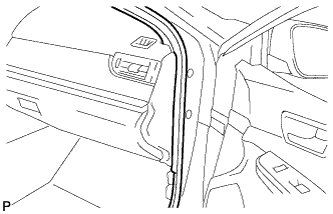
DISCONNECT FRONT DOOR OPENING TRIM WEATHERSTRIP LH
-
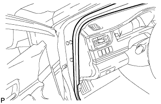
Disconnect the front door opening trim weatherstrip LH.
-
-
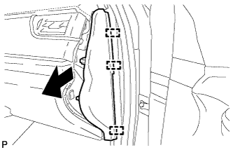
REMOVE INSTRUMENT SIDE PANEL LH
-
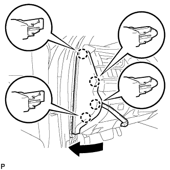
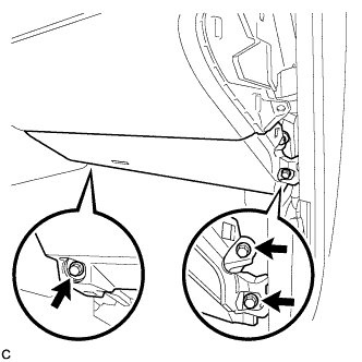
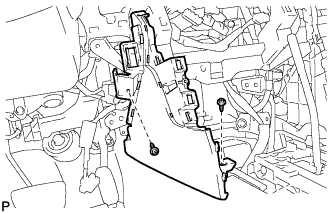
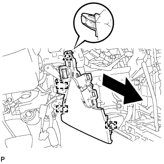
Using a moulding remover, disengage the 4 claws as shown in the illustration.
-
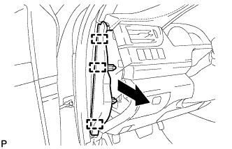
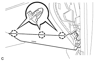
Disengage the 3 guides and remove the instrument side panel LH as shown in the illustration.
-
-
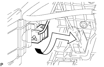
DISCONNECT HOOD LOCK CONTROL LEVER SUB-ASSEMBLY
-
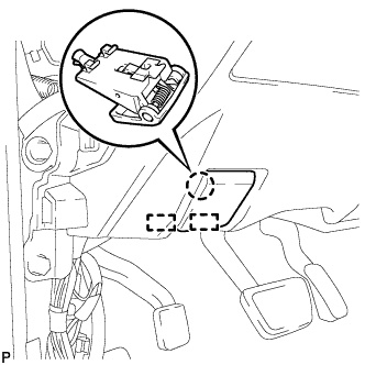
Disengage the claw and 2 guides to disconnect the hood lock control lever sub-assembly.
-
-
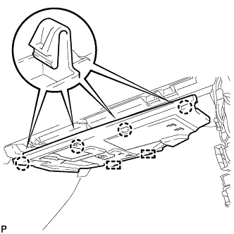
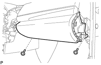
REMOVE LOWER NO. 1 INSTRUMENT PANEL FINISH PANEL ASSEMBLY
-
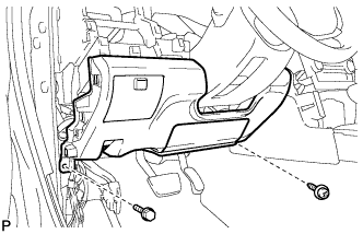
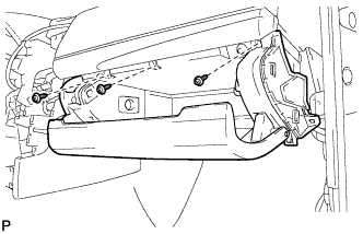
Remove the bolt <C> and screw <D> or <E>.
-
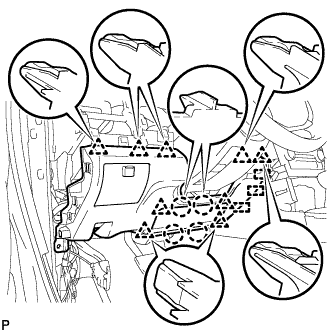
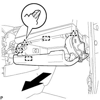
Disengage the 4 claws, 9 clips and 3 guides to remove the lower No. 1 instrument panel finish panel assembly.
-
-
REMOVE FRONT DOOR SCUFF PLATE RH
Tech Tips
Use the same procedure as for the LH side.
-
REMOVE COWL SIDE TRIM SUB-ASSEMBLY RH
Tech Tips
Use the same procedure as for the LH side.
-
DISCONNECT FRONT DOOR OPENING TRIM WEATHERSTRIP RH
-
Disconnect the front door opening trim weatherstrip RH.
-
-
REMOVE INSTRUMENT SIDE PANEL RH
-
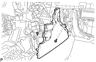
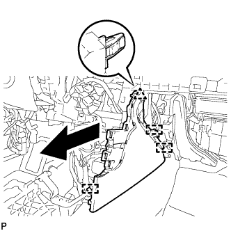
Using a moulding remover, disengage the 4 claws as shown in the illustration.
-
Disengage the 3 guides to remove the instrument side panel RH as shown in the illustration.
-
-
REMOVE NO. 2 INSTRUMENT PANEL UNDER COVER SUB-ASSEMBLY
-
Disengage the 4 claws and 2 guides.
-
Disconnect the connector and remove the No. 2 instrument panel under cover sub-assembly.
-
-
REMOVE LOWER NO. 2 INSTRUMENT PANEL AIRBAG ASSEMBLY
CAUTION:
When storing the lower No. 2 instrument panel airbag assembly, keep the airbag deployment side facing upward.
-
Check that the power switch is off.
-
Check that the cable is disconnected from the negative (-) auxiliary battery terminal.
CAUTION:
Wait at least 90 seconds after disconnecting the cable from the negative (-) auxiliary battery terminal to disable the SRS system.
-
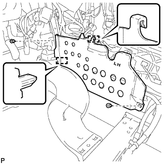
Remove the 3 bolts.
-
Disengage the 3 claws to remove the lower No. 2 instrument panel airbag assembly.
Note
When removing the lower No. 2 instrument panel airbag assembly, do not pull the airbag wire harness.
-
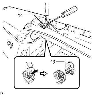
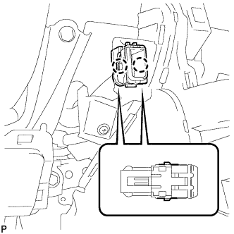
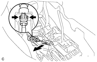
Text in Illustration *1 Protective Tape *2 Airbag Connector *3 Airbag Connector Lock Using a screwdriver with the tip wrapped with protective tape, release the airbag connector lock.
-
Disconnect the airbag connector to remove the lower No. 2 instrument panel airbag assembly.
Note
When disconnecting any airbag connector, take care not to damage the airbag wire harness.
-
-
REMOVE LOWER INSTRUMENT PANEL SUB-ASSEMBLY
-
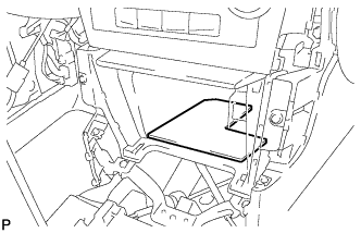
Remove the 2 screws <D> or <E>.
-
Open the lower instrument panel door.
-
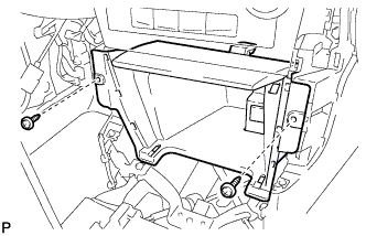
Remove the 3 screws <D> or <E>.
-
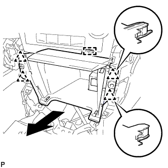
Disengage the 2 clips and 3 guides.
-
Disengage the glove compartment light as shown in the illustration.
-
Disconnect each connector and remove the lower instrument panel sub-assembly.
-
-
REMOVE BOX BOTTOM MAT
-
Remove the box bottom mat.
-
-
REMOVE UPPER CONSOLE PANEL SUB-ASSEMBLY
-
Remove the 2 screws <D> or <E>.
-
Disengage the 4 clips and guide as shown in the illustration.
-
Disconnect each connector to remove the upper console panel sub-assembly.
-
-
REMOVE FRONT NO. 2 CONSOLE BOX INSERT
-
Disengage the 2 claws to disconnect the room temperature sensor from the front No. 2 console box insert.
-
Remove the 2 screws <D> or <E>.
-
Disengage the clip and 3 guides to remove the front No. 2 console box insert as shown in the illustration.
-
-
REMOVE CONSOLE BOX INSERT
-
Remove the 2 screws <D> or <E>.
-
Disengage the clip and 3 guides to remove the console box insert as shown in the illustration.
-
-
REMOVE FLOOR CARPET BRACKET LH
-
Remove the 2 clips.
-
Disengage the 2 guides to remove the floor carpet bracket LH.
-
-
REMOVE NO. 1 CONSOLE BOX MOUNTING BRACKET
-
Remove the screw and No. 1 console box mounting bracket from the lower shift lever assembly.
-
-
REMOVE NO. 1 CONSOLE BOX DUCT
-
Remove the clip and No. 1 console box duct.
-
-
REMOVE LOWER SHIFT LEVER ASSEMBLY
-
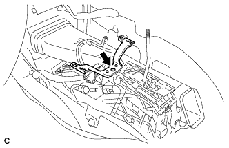
Disconnect the end of transmission control cable assembly from the lower shift lever assembly.
-
Disengage the 2 claws and disconnect the transmission control cable assembly from the lower shift lever assembly.
-
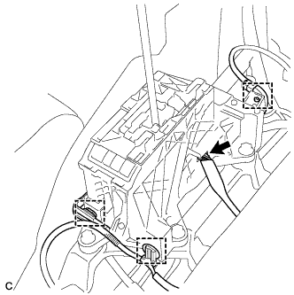
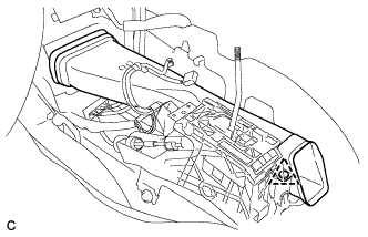
Disconnect the 3 clamps and connector.
-
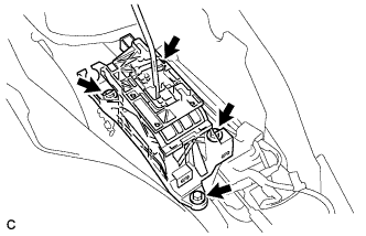
Remove the 4 bolts and lower shift lever assembly.
-
-
REMOVE SHIFT LEVER SUPPORT
-
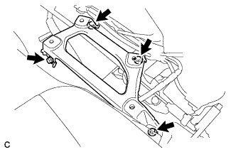
Remove the 4 bolts and shift lever support.
-