REAR AXLE CARRIER REMOVAL

Note
When the brake pedal is first depressed after replacing the brake pads or pushing back the disc brake piston, DTC C1214 may be output. As there is no malfunction, clear the DTC.
Tech Tips
-
Use the same procedure for the RH side and LH side.
-
The procedure listed below is for the LH side.
-
PRECAUTION
Note
After turning the power switch off, waiting time may be required before disconnecting the cable from the negative (-) auxiliary battery terminal. Therefore, make sure to read the disconnecting the cable from the negative (-) auxiliary battery terminal notice before proceeding with work Click here.
-
DISABLE BRAKE CONTROL
-
Wait at least 2 minutes after turning the power switch off.
Note
When the brake pedal is depressed or the door courtesy switch is turned on even if the power switch is off, the brake control system activates. Therefore do not depress the brake pedal or open/close the doors until the reservoir level switch connector is disconnected.
-
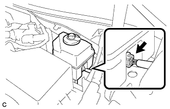
Disconnect the reservoir level switch connector with the parking brake applied.
-
Disconnect the cable from the negative (-) auxiliary battery terminal Click here.
-
Depress the brake pedal 40 times or more to return all the fluid in the accumulator back to the reservoir.
-
Check that the brake pedal can not be further depressed.
-
Release the parking brake.
-
-
REMOVE REAR WHEEL
-
SEPARATE REAR DISC BRAKE CALIPER ASSEMBLY
-
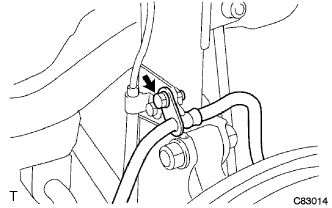
Remove the bolt and separate the rear flexible hose from the rear shock absorber.
-
Remove the 2 bolts, and separate the rear disc brake caliper assembly.
Note
Use wire or an equivalent tool to keep the rear disc brake caliper from hanging down by the flexible hose.
-
-
REMOVE PARKING BRAKE SHOE ADJUSTING HOLE PLUG
-
Remove the parking brake shoe adjusting hole plug.
-
-
REMOVE REAR DISC
-
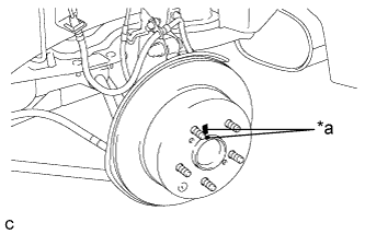
Text in Illustration *a Matchmark Put matchmarks on the rear disc and the rear axle hub.
-
Release the parking brake and remove the rear disc.
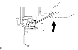
Tech Tips
If the disc cannot be removed easily, use a screwdriver to turn the shoe adjuster as shown in the illustration in order to contract the parking brake shoes.
-
-
DISCONNECT SKID CONTROL SENSOR WIRE
-
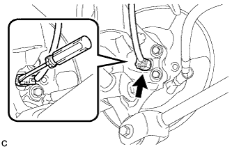
Using a screwdriver, disconnect the connector from the rear axle hub and bearing assembly.
Note
Be careful not to damage the rear speed sensor.
-
-
REMOVE REAR AXLE HUB AND BEARING ASSEMBLY
-
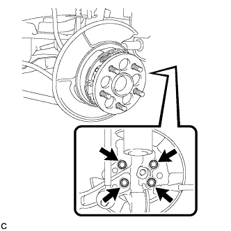
Remove the 4 bolts and the rear axle hub and bearing assembly from the rear axle carrier sub-assembly.
Note
Use wire or an equivalent tool to keep the parking brake assembly from hanging down by the parking brake cable assembly.
-
-
REMOVE REAR HEIGHT CONTROL SENSOR SUB-ASSEMBLY (w/ Height Control Sensor)
Tech Tips
It is necessary to remove the rear height control sensor sub-assembly when separating the rear No. 2 suspension arm assembly RH.
-
SEPARATE REAR STRUT ROD ASSEMBLY
-
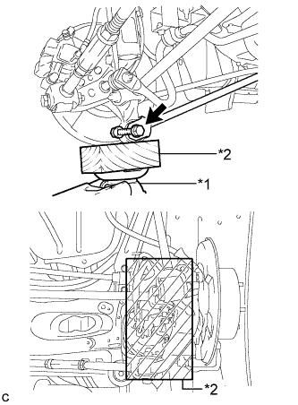
Text in Illustration *1 Jack *2 Wooden Block Use a jack and wooden block to support the rear axle carrier sub-assembly.
-
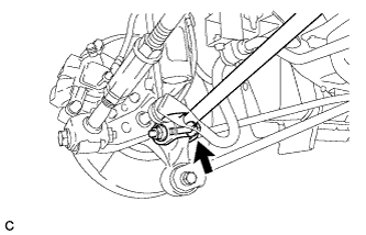
Remove the bolt and nut, and separate the rear strut rod assembly (rear side) from the rear axle carrier sub-assembly.
Note
When removing the bolt, keep the nut from rotating.
-
-
SEPARATE REAR NO. 2 SUSPENSION ARM ASSEMBLY
-
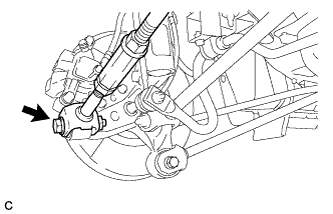
Remove the bolt and nut, and separate the rear No. 2 suspension arm assembly (outer side) from the rear axle carrier sub-assembly.
Note
When removing the bolt, keep the nut from rotating.
-
-
SEPARATE REAR NO. 1 SUSPENSION ARM ASSEMBLY
-
Remove the bolt and nut, and separate the rear No. 1 suspension arm assembly (outer side) from the rear axle carrier sub-assembly.
Note
When removing the bolt, keep the nut from rotating.
-
-
REMOVE REAR AXLE CARRIER SUB-ASSEMBLY
-
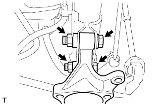
Remove the 2 bolts, 2 nuts and rear axle carrier sub-assembly from the rear shock absorber.
Note
When removing the nuts, keep the bolts from rotating.
-