HYBRID VEHICLE TRANSAXLE INSTALLATION

-
INSTALL WITH HEAD STRAIGHT SCREW PLUG
Tech Tips
Perform this procedure only when replacement of the with head straight screw plug is necessary.
-
Coat a new O-ring with ATF and install it to the with head straight screw plug.
-
Using a 10 mm hexagon socket wrench, install the with head straight screw plug to the hybrid vehicle transaxle assembly.
- Torque:
- 25 N*m { 250 kgf*cm, 18 ft.*lbf }
-
-
INSTALL NO. 1 INVERTER COOLING HOSE ASSEMBLY
-
Install the No. 1 inverter cooling hose assembly to the hybrid vehicle transaxle assembly.
-
-
INSTALL WIRE HARNESS CLAMP BRACKET
-
Install the 2 wire harness clamp brackets to the hybrid vehicle transaxle assembly with the 3 bolts.
- Torque:
- 8.0 N*m { 82 kgf*cm, 71 in.*lbf }
-
-
INSTALL HYBRID TRANSAXLE MASS DAMPER
-
Install a new gasket and the hybrid transaxle mass damper.
- Torque:
- 39 N*m { 400 kgf*cm, 29 ft.*lbf }
-
-
INSTALL NO. 3 AUTOMATIC TRANSMISSION CASE COVER
-
Install the No. 3 automatic transmission case cover to the hybrid vehicle transaxle assembly with the 2 bolts and a new clip.
- Torque:
- 7.0 N*m { 71 kgf*cm, 62 in.*lbf }
-
-
INSTALL AUTOMATIC TRANSMISSION CASE COVER
-
Engage the 2 guides and install the automatic transmission case cover.
-
-
INSTALL NO. 3 TRANSMISSION CONTROL CABLE BRACKET
-
Install the No. 3 transmission control cable bracket to the hybrid vehicle transaxle assembly with the bolt.
- Torque:
- 12 N*m { 122 kgf*cm, 9 ft.*lbf }
-
-
INSTALL NO. 2 TRANSMISSION CONTROL CABLE BRACKET
-
Install the No. 2 transmission control cable bracket to the hybrid vehicle transaxle assembly with the bolt.
- Torque:
- 12 N*m { 122 kgf*cm, 9 ft.*lbf }
-
-
INSTALL NO. 1 TRANSMISSION CONTROL CABLE BRACKET
-
Install the No. 1 transmission control cable bracket to the hybrid vehicle transaxle assembly with the 2 bolts.
- Torque:
- 12 N*m { 122 kgf*cm, 9 ft.*lbf }
-
-
INSTALL FRONT ENGINE MOUNTING BRACKET
-
Install the front engine mounting bracket to the hybrid vehicle transaxle assembly with the 3 bolts.
- Torque:
- 64 N*m { 653 kgf*cm, 47 ft.*lbf }
-
-
INSTALL HYBRID VEHICLE TRANSAXLE ASSEMBLY
-
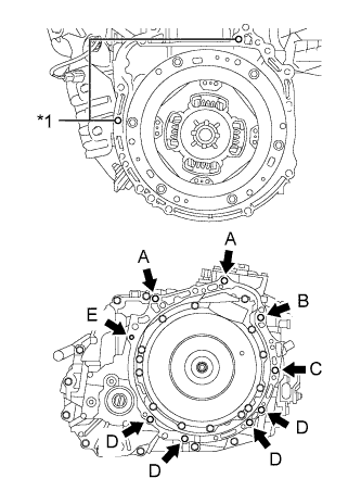
Text in Illustration *1 Knock Pin Make sure that the 2 knock pins are installed to the engine assembly.
-
Install the hybrid vehicle transaxle assembly to the engine assembly with the 9 bolts.
Bolt Bolt Length Torque (A), (B) 55 mm (2.17 in.) 64 N*m (653 kgf*cm, 47 ft.*lbf) (C) 65 mm (2.56 in.) 46 N*m (469 kgf*cm, 34 ft.*lbf) (D) 32 mm (1.26 in.) 44 N*m (449 kgf*cm, 32 ft.*lbf) 33 mm (1.30 in.) 43 N*m (438 kgf*cm, 32 ft.*lbf) (E) 38 mm (1.50 in.) 28 N*m (286 kgf*cm, 21 ft.*lbf) Note
-
Do not apply grease either to the inner splines or to the input shaft assembly.
-
Make sure that the wire harness or similar items are not pinched between the contact surfaces.
-
Do not use excessive force when installing the hybrid vehicle transaxle assembly.
-
Make sure to align the hybrid vehicle transaxle assembly so that the input shaft assembly of the hybrid vehicle transaxle assembly will be inserted straight into the inner splines of the transmission input damper assembly.
-
When inserting the input shaft assembly of the hybrid vehicle transaxle assembly into the inner splines of the transmission input damper assembly, do not shake the hybrid vehicle transaxle assembly excessively.
-
When mounting the hybrid vehicle transaxle assembly to the engine assembly, make sure to securely fit the 2 knock pins into the knock holes.
Tech Tips
Temporarily install bolt B first.
-
-
-
INSTALL FRONT FRAME ASSEMBLY
-
Install the engine mounting insulator LH with the nut.
- Torque:
- 95 N*m { 969 kgf*cm, 70 ft.*lbf }
-
Install the engine mounting insulator RH with the nut.
- Torque:
- 95 N*m { 969 kgf*cm, 70 ft.*lbf }
-
Install the front engine mounting insulator with the bolt.
- Torque:
- 87 N*m { 887 kgf*cm, 64 ft.*lbf }
-
Fully tighten the 9 temporarily installed nuts of the engine mounting insulators to the specified torque.
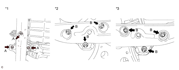
Text in Illustration *1 Front Engine Mounting Insulator *2 Engine Mounting Insulator RH *3 Engine Mounting Insulator LH - - - Torque:
- A
- 58 N*m { 591 kgf*cm, 43 ft.*lbf }
- B
- 99 N*m { 1010 kgf*cm, 73 ft.*lbf }
Tech Tips
Perform this procedure only when replacement of the engine mounting insulator is necessary.
-
Install the 4 hole plugs.
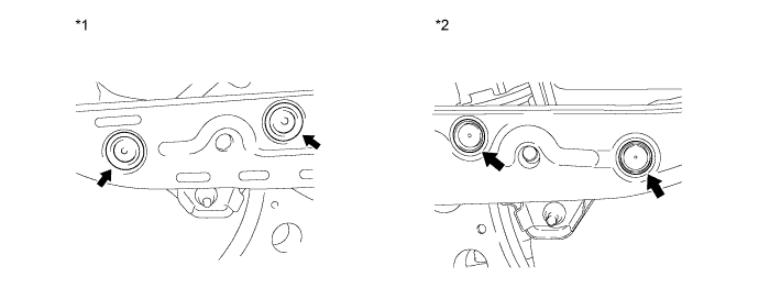
Text in Illustration *1 Engine Mounting Insulator RH *2 Engine Mounting Insulator LH Tech Tips
Perform this procedure only when replacement of the engine mounting insulator is necessary.
-
Connect the No. 4 engine wire to the front frame assembly with the bolt.
- Torque:
- 8.0 N*m { 82 kgf*cm, 71 in.*lbf }
-
-
CONNECT WIRE HARNESS
-
Connect the 3 clamps and install the motor cable to the hybrid vehicle transaxle assembly with the bolt.
- Torque:
- 8.0 N*m { 82 kgf*cm, 71 in.*lbf }
-
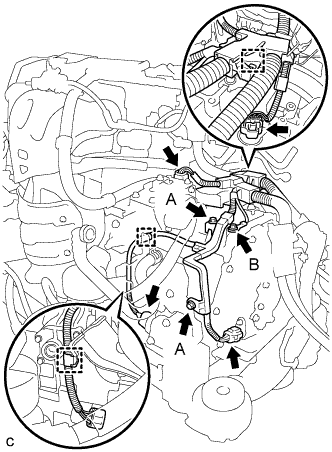
Connect the 3 clamps, 4 connectors and install the wire harness to the hybrid vehicle transaxle assembly with the 3 bolts.
- Torque:
- Bolt (A)
- 8.0 N*m { 82 kgf*cm, 71 in.*lbf }
- Torque:
- Bolt (B)
- 12 N*m { 122 kgf*cm, 9 ft.*lbf }
-
-
INSTALL ENGINE ASSEMBLY WITH TRANSAXLE