INTAKE MANIFOLD REMOVAL

-
PRECAUTION
Note
After turning the power switch off, waiting time may be required before disconnecting the cable from the negative (-) auxiliary battery terminal. Therefore, make sure to read the disconnecting the cable from the negative (-) auxiliary battery terminal notice before proceeding with work Click here.
-
DISCHARGE FUEL SYSTEM PRESSURE
-
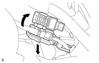
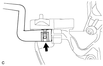
REMOVE LUGGAGE TRIM SERVICE HOLE COVER
-
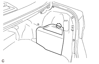
Disengage the claw to remove the luggage trim service hole cover.
-
-
DISCONNECT CABLE FROM NEGATIVE AUXILIARY BATTERY TERMINAL
Note
When disconnecting the cable, some systems need to be initialized after the cable is reconnected Click here.
-
REMOVE THROTTLE WITH MOTOR BODY ASSEMBLY
-
REMOVE WINDSHIELD WIPER MOTOR AND LINK ASSEMBLY
-
REMOVE FRONT OUTER COWL TOP PANEL SUB-ASSEMBLY
-
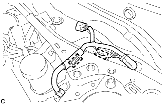
Disengage the 2 clamps and separate the wire harness from the front outer cowl top panel sub-assembly.
-
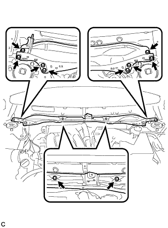
Remove the 10 bolts and front outer cowl top panel sub-assembly.
-
-
REMOVE EGR VALVE ASSEMBLY
-
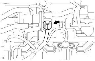
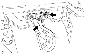
Disconnect the connector.
-

Disconnect the 2 water by-pass hoses.
-
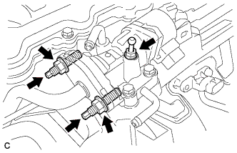
Using a 10 mm deep socket wrench, remove the bolt.
-
Using a 12 mm deep socket wrench, remove the 2 nuts.
-
Using an E8 "TORX" socket wrench, remove the 2 stud bolts.
-
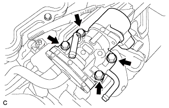
Remove the 4 bolts and EGR valve assembly.
-
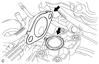
Remove the 2 gaskets.
-
-
REMOVE MANIFOLD ABSOLUTE PRESSURE SENSOR
-
Disconnect the connector.
-
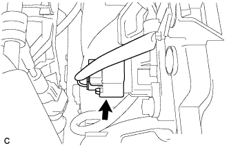
Disconnect the vacuum hose.
-
Remove the bolt and manifold absolute pressure sensor.
-
-
SEPARATE INTAKE MANIFOLD
-
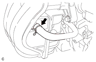
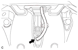
Disconnect the No. 2 ventilation hose.
-
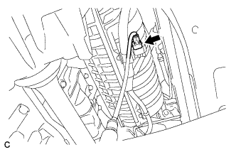
Disconnect the heated oxygen sensor connector.
-
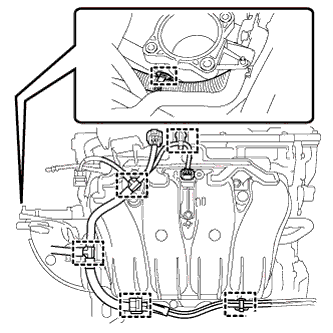
Disconnect the 6 wire harness clamps.
-
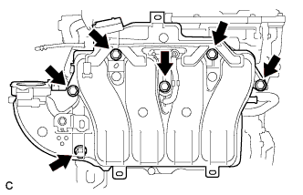
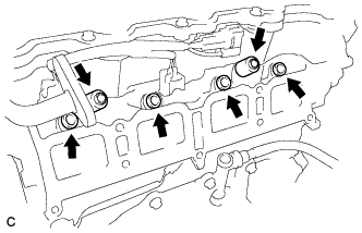
Remove the 6 bolts to separate the intake manifold from the engine assembly.
-
-
DISCONNECT FUEL TUBE SUB-ASSEMBLY
-
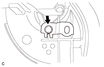
Remove the No. 1 fuel pipe clamp.
-
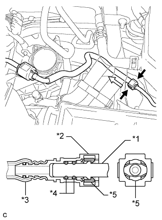
Text in Illustration *1 Fuel Pipe *2 Fuel Tube Connector *3 Nylon Tube *4 O-ring *5 Retainer 
Pinch 
Pull Pinch the retainer of the fuel tube connector, and then pull the fuel tube connector off of the fuel pipe.
Note
-
Check for foreign matter on the fuel tube around the fuel tube connector. Clean it if necessary. Foreign matter can affect the ability of the O-ring to seal the fuel tube connector and fuel pipe.
-
Do not use any tools to separate the fuel tube connector and fuel pipe.
-
Do not forcefully bend, kink or twist the nylon tube.
-
Keep the fuel tube connector and fuel pipe free from foreign matter.
-
If the fuel tube connector and fuel pipe are stuck, push and pull to release them.
-
Put the fuel tube connector and fuel pipe in plastic bags to prevent damage and contamination.
-
-
Remove the fuel tube sub-assembly from the fuel hose clamp.
-
-
REMOVE FUEL DELIVERY PIPE SUB-ASSEMBLY
-
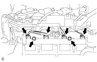
Disconnect the 4 fuel injector connectors.
-
Remove the 2 bolts, and then remove the fuel delivery pipe together with the 4 fuel injectors.
Note
Be careful not to drop the fuel injectors when removing the fuel delivery pipe.
-
Remove the 2 fuel delivery spacers from the cylinder head.
-
Remove the 4 injector vibration insulators from the cylinder head.
-
-
REMOVE INTAKE MANIFOLD
-
Remove the intake manifold from the vehicle.
-
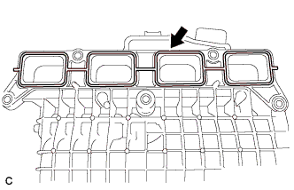
Remove the gasket from the intake manifold.
-
Remove the bolt and wire harness clamp bracket.
-
Remove the vacuum hose from the intake manifold.
-
Remove the fuel vapor feed hose from the intake manifold.
-