CYLINDER BLOCK INSPECTION

-
INSPECT CYLINDER BLOCK FOR WARPAGE
-
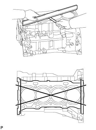
Using a precision straightedge and feeler gauge, measure the warpage of the cylinder head gasket contact surface.
Maximum Warpage 0.05 mm (0.00197 in.) If the warpage is more than the maximum, replace the cylinder block sub-assembly.
-
-
INSPECT CYLINDER BORE
-
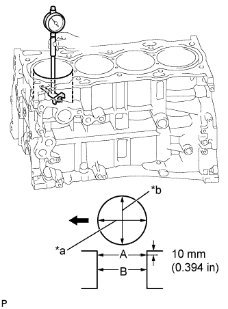
Text in Illustration *a Axial Direction *b Thrust Direction 
Front Using a cylinder gauge, measure the cylinder bore diameter at positions (A) and (B) in the thrust and axial directions.
Standard Diameter 90.000 to 90.013 mm (3.543 to 3.544 in.) Maximum Diameter 90.13 mm (3.548 in.) If the average diameter of the 4 positions is more than the maximum, replace the cylinder block sub-assembly.
-
-
INSPECT PISTON
-
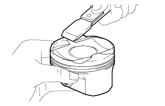
Using a gasket scraper, remove the carbon from the piston top.
-
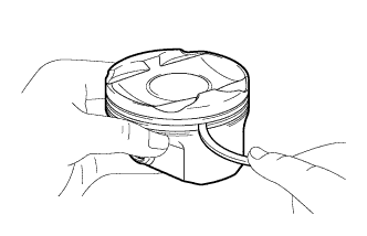
Using a groove cleaning tool or a broken ring, clean the piston ring grooves.
-
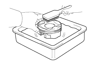
Using a brush and solvent, thoroughly clean the piston.
Note
Do not use a wire brush.
-
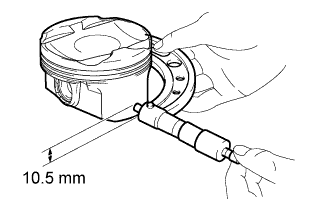
Using a micrometer, measure the piston diameter at a right angle to the piston center line, and at a position that is 10.5 mm (0.413 in.) from the bottom of the piston.
Standard Piston Diameter 89.980 to 89.995 mm (3.5425 to 3.5431 in.) If the diameter is less than the minimum, replace the piston.
-
-
INSPECT PISTON OIL CLEARANCE
-
Measure the cylinder bore diameter in the thrust direction.
-
Subtract the piston diameter measurement from the cylinder bore diameter measurement.
Standard Oil Clearance 0.004 to 0.043 mm (0.000158 to 0.00169 in.) Maximum Oil Clearance 0.10 mm (0.00394 in.) If the oil clearance is more than the maximum, replace all the pistons. If necessary, replace the cylinder block sub-assembly.
-
-
INSPECT RING GROOVE CLEARANCE
-
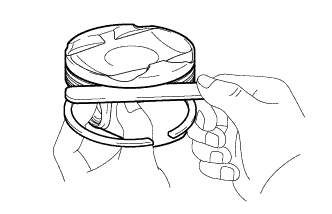
Using a feeler gauge, measure the clearance between the new piston ring and the wall of the ring groove.
Standard Ring Groove Clearance Item Specified Condition No. 1 ring 0.020 to 0.070 mm (0.000787 to 0.00276 in.) No. 2 ring 0.020 to 0.060 mm (0.000787 to 0.00236 in.) Oil ring 0.020 to 0.070 mm (0.000787 to 0.00276 in.) If the groove clearance is not as specified, replace the piston.
-
-
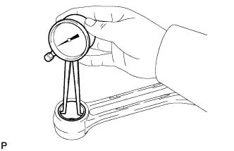
INSPECT PISTON RING END GAP
-
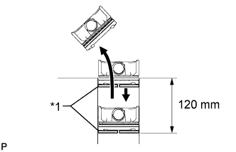
Text in Illustration *1 Piston Ring Insert the piston ring into the cylinder bore.
-
Using a piston, push the piston ring a little beyond the bottom of the ring travel, 120 mm (4.72 in.) from the top of the cylinder block sub-assembly.
-
Using a feeler gauge, measure the end gap.
Standard End Gap Item Specified Condition No. 1 ring 0.22 to 0.27 mm (0.00866 to 0.0106 in.) No. 2 ring 0.37 to 0.42 mm (0.0146 to 0.0165 in.) Oil ring 0.10 to 0.20 mm (0.00394 to 0.00787 in.) Maximum End Gap Item Specified Condition No. 1 ring 0.87 mm (0.0343 in.) No. 2 ring 1.02 mm (0.0402 in.) Oil ring 0.80 mm (0.0315 in.) If the end gap is more than the maximum, replace the piston ring. If the end gap is more than the maximum, even with a new piston ring, replace the cylinder block sub-assembly.
-
-
INSPECT PISTON PIN OIL CLEARANCE
-
Check each mark on the piston, piston pin and connecting rod sub-assembly.
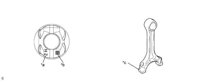
Text in Illustration *a Front Mark *b Piston Pin Hole Inside Diameter Mark *c Connecting Rod Small End Bush Inside Diameter Mark - - Tech Tips
The front mark is "2H" printed in raised letters.
-
Using a caliper gauge, measure the inside diameter of the piston pin hole.
Standard Piston Pin Hole Inside Diameter Item Specified Condition Mark A 22.001 to 22.004 mm (0.86618 to 0.86630 in.) Mark B 22.005 to 22.007 mm (0.86634 to 0.86642 in.) Mark C 22.008 to 22.010 mm (0.86645 to 0.86653 in.) -
Using a micrometer, measure the piston pin diameter.
Standard Piston Pin Diameter Item Specified Condition Mark A 21.997 to 22.000 mm (0.86602 to 0.86614 in.) Mark B 22.001 to 22.003 mm (0.86618 to 0.86626 in.) Mark C 22.004 to 22.006 mm (0.86630 to 0.86638 in.) If the diameter is not as specified, replace the piston pin.
-
Using a caliper gauge, measure the connecting rod small end bush inside diameter.
Standard Connecting Rod Small End Bush Inside Diameter Item Specified Condition Mark A 22.005 to 22.008 mm (0.86634 to 0.86645 in.) Mark B 22.009 to 22.011 mm (0.86649 to 0.86657 in.) Mark C 22.012 to 22.014 mm (0.86661 to 0.86669 in.) If the diameter is not as specified, replace the connecting rod sub-assembly.
-
Subtract the piston pin diameter measurement from the piston pin hole inside diameter measurement.
Standard Oil Clearance 0.001 to 0.007 mm (0.0000394 to 0.000276 in.) Maximum Oil Clearance 0.013 mm (0.000512 in.) If the oil clearance is more than the maximum, replace the piston and piston pin as a set.
-
Subtract the piston pin diameter measurement from the connecting rod small end bush inside diameter measurement.
Standard Oil Clearance 0.005 to 0.011 mm (0.000197 to 0.000433 in.) Maximum Oil Clearance 0.017 mm (0.000669 in.) If the oil clearance is more than the maximum, replace the connecting rod sub-assembly. If necessary, replace the connecting rod sub-assembly and piston pin as a set.
-
-
INSPECT CONNECTING ROD SUB-ASSEMBLY
-
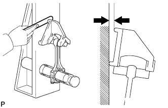
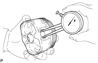
Using a connecting rod aligner and feeler gauge, check the connecting rod alignment.
-
Check for bend.
Maximum Bend 0.05 mm (0.00197 in.) per 100 mm (3.94 in.) If the bend is more than the maximum, replace the connecting rod sub-assembly.
-
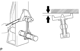
Check for twist.
Maximum Twist 0.15 mm (0.00591 in.) per 100 mm (3.94 in.) If the twist is more than the maximum, replace the connecting rod sub-assembly.
-
-
-
INSPECT CRANKSHAFT
-
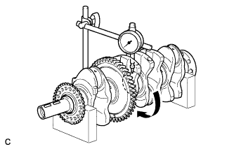
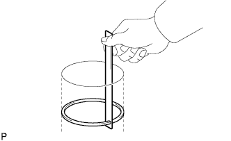
Inspect for circle runout.
-
Using a dial indicator and V-blocks, measure the circle runout as shown in the illustration.
Maximum Circle Runout 0.003 mm (0.000118 in.) If the circle runout is more than the maximum, replace the crankshaft.
-
-
Inspect the main journals.
-
Using a micrometer, measure the diameter of each main journal.
Standard Main Journal Diameter 54.988 to 55.000 mm (2.1649 to 2.1654 in.) If the diameter is not as specified, check the crankshaft oil clearance. If necessary, replace the crankshaft.
-
Check each main journal for taper and out-of-round as shown in the illustration.
Maximum Taper and Out-of-round 0.003 mm (0.000118 in.) If the taper or out-of-round is more than the maximum, replace the crankshaft.
-
-
Inspect the crank pin.
-
Using a micrometer, measure the diameter of each crank pin.
Standard Crank Pin Diameter 51.492 to 51.500 mm (2.027 to 2.028 in.) If the diameter is not as specified, check the connecting rod oil clearance. If necessary, replace the crankshaft.
-
Inspect each crank pin for taper and out-of-round as shown in the illustration.
Maximum Taper and Out-of-round 0.003 mm (0.000118 in.) If the taper or out-of-round is more than the maximum, replace the crankshaft.
-
-
-
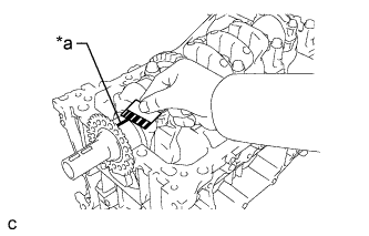
INSPECT CRANKSHAFT OIL CLEARANCE
-
Install the crankshaft bearings Click here.
-
Install the crankshaft thrust washers Click here.
-
Place the crankshaft onto the cylinder block sub-assembly.
-
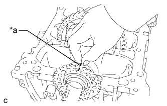
Text in Illustration *a Plastigage Lay a strip of Plastigage across each journal.
-
Install the crankshaft bearing caps Click here.
Note
Do not turn the crankshaft.
-
Remove the crankshaft bearing caps Click here.
-
Text in Illustration *a Plastigage Measure the Plastigage at its widest point.
Standard Oil Clearance 0.017 to 0.040 mm (0.000669 to 0.00157 in.) Maximum Oil Clearance 0.05 mm (0.00197 in.) Note
Remove the Plastigage completely after the measurement.
If the oil clearance is more than the maximum, replace the crankshaft bearing. If necessary, replace the crankshaft.
Tech Tips
If replacing a crankshaft bearing, select a new one with the same number. If the number of the crankshaft bearing cannot be determined, calculate the correct crankshaft bearing number by adding together the numbers imprinted on the cylinder block sub-assembly and crankshaft. Then select a new crankshaft bearing with the calculated number. There are 4 sizes of standard crankshaft bearings, marked "1", "2", "3" or "4" accordingly.
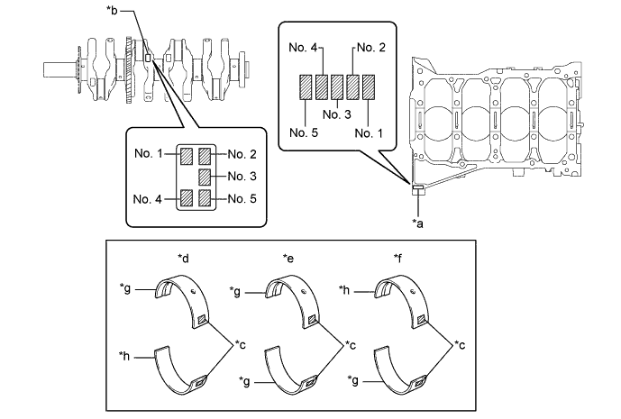
Text in Illustration *a Cylinder Block Number Mark (A) *b Crankshaft Number Mark (B) *c Diameter Mark *d No. 1, No. 5 Journal Bearing *e No. 2, No. 4 Journal Bearing *f No. 3 Journal Bearing *g Silver *h Black
-
EXAMPLE
Cylinder block (A) "3" + Crankshaft (B) "4" = Total "7"
Select the crankshaft bearing marked "3".
Bearing Chart (A) + (B) Use Crankshaft Bearing 0 to 2 1 3 to 5 2 6 to 8 3 9 to 11 4 Standard Cylinder Block Journal Inside Diameter (A) Item Specified Condition Mark 0 59.000 to 59.002 mm (2.32283 to 2.32291 in.) Mark 1 59.003 to 59.004 mm (2.32295 to 2.32299 in.) Mark 2 59.005 to 59.006 mm (2.32303 to 2.32307 in.) Mark 3 59.007 to 59.009 mm (2.32311 to 2.32318 in.) Mark 4 59.010 to 59.011 mm (2.32322 to 2.32326 in.) Mark 5 59.012 to 59.013 mm (2.32330 to 2.32334 in.) Mark 6 59.014 to 59.016 mm (2.32338 to 2.32346 in.) Standard Crankshaft Main Journal Diameter (B) Item Specified Condition Mark 0 54.999 to 55.000 mm (2.16531 to 2.16535 in.) Mark 1 54.997 to 54.998 mm (2.16523 to 2.16527 in.) Mark 2 54.995 to 54.996 mm (2.16515 to 2.16519 in.) Mark 3 54.993 to 54.994 mm (2.16507 to 2.16511 in.) Mark 4 54.991 to 54.992 mm (2.16500 to 2.16504 in.) Mark 5 54.988 to 54.990 mm (2.16488 to 2.16496 in.) Standard Crankshaft Bearing (Silver) Center Wall Thickness Item Specified Condition Mark 1 1.991 to 1.994 mm (0.07839 to 0.07850 in.) Mark 2 1.995 to 1.997 mm (0.07854 to 0.07862 in.) Mark 3 1.998 to 2.000 mm (0.07866 to 0.07874 in.) Mark 4 2.001 to 2.003 mm (0.07878 to 0.07886 in.) Standard Crankshaft Bearing (Black) Center Wall Thickness Item Specified Condition Mark 1 1.992 to 1.995 mm (0.07843 to 0.07854 in.) Mark 2 1.996 to 1.998 mm (0.07858 to 0.07866 in.) Mark 3 1.999 to 2.001 mm (0.07870 to 0.07878 in.) Mark 4 2.002 to 2.004 mm (0.07882 to 0.07890 in.)
-
-
Perform the inspection above for each journal.
-
-
INSPECT CRANKSHAFT BEARING CAP BOLT
-
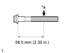
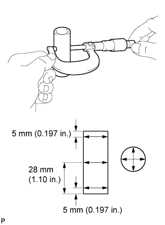
Text in Illustration *a Measurement Point Using a vernier caliper, measure the diameter of the threads at the measurement point shown in the illustration.
Standard Diameter 9.77 to 9.96 mm (0.385 to 0.392 in.) Minimum Diameter 9.1 mm (0.358 in.) Tech Tips
-
If the diameter is less than the minimum, replace the crankshaft bearing cap bolt. Failure to do so may lead to engine damage.
-
If there is any thread deformation, replace the crankshaft bearing cap bolt with a new one.
-
-
-
INSPECT CONNECTING ROD BOLT
-
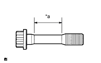
Text in Illustration *a Measurement Area Using a vernier caliper, measure the diameter of the connecting rod bolt in the area shown in the illustration.
Standard Diameter 8.5 to 8.6 mm (0.335 to 0.339 in.) Minimum Diameter 8.3 mm (0.327 in.) Tech Tips
-
Diameter measurements should be done at several points.
-
If the diameter is less than the minimum, replace the connecting rod bolt with a new one. Failure to do so may lead to engine damage.
-
If there is any thread deformation, replace the connecting rod bolt with a new one.
-
-
-
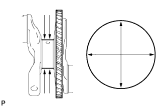
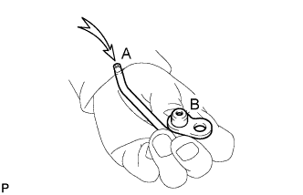
INSPECT NO. 1 OIL NOZZLE SUB-ASSEMBLY
-
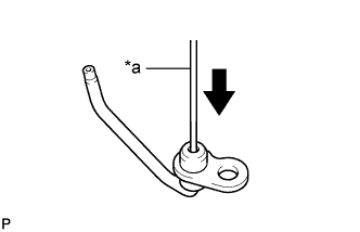
Text in Illustration *a Pin Push the check valve with a pin to check if it is stuck.
If stuck, replace the No. 1 oil nozzle sub-assembly.
-
Push the check valve with a pin to check if it moves smoothly.
If it does not move smoothly, clean or replace the No. 1 oil nozzle sub-assembly.
-
Apply air into (A). Check that air does not leak through (B).
If air leaks, clean or replace the No. 1 oil nozzle sub-assembly.
-
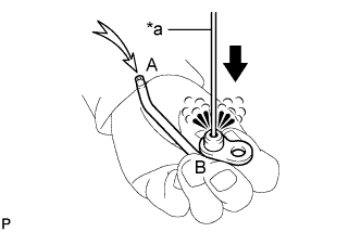
Text in Illustration *a Pin Push the check valve with a pin while applying air into (A). Check that air passes through (B).
If air does not pass through (B), clean or replace the No. 1 oil nozzle sub-assembly.
-
-
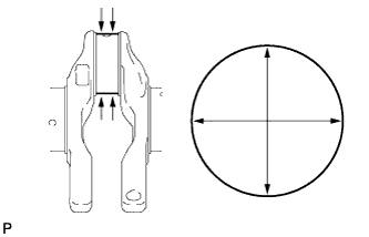
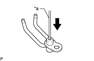
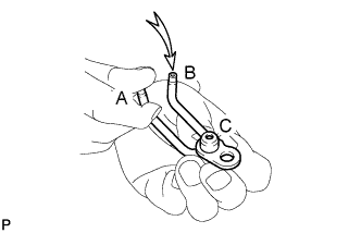
INSPECT NO. 2 OIL NOZZLE SUB-ASSEMBLY
-
Text in Illustration *a Pin Push the check valve with a pin to check if it is stuck.
If stuck, replace the No. 2 oil nozzle sub-assembly.
-
Push the check valve with a pin to check if it moves smoothly.
If it does not move smoothly, clean or replace the No. 2 oil nozzle sub-assembly.
-
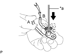
While covering (A), apply air into (B). Check that air does not leak through (C). Perform the check again while covering (B) and applying air into (A).
If air leaks, clean or replace the No. 2 oil nozzle sub-assembly.
-
Text in Illustration *a Pin Push the check valve with a pin while covering (A), and apply air into (B). Check that air passes through (C). Perform the check again while covering (B), pushing the check valve and applying air into (A).
If air does not pass through (C), clean or replace the No. 2 oil nozzle sub-assembly.
-