ENGINE UNIT INSTALLATION

Tech Tips
Perform "Inspection After Repair" after replacing the engine assembly Click here.
-
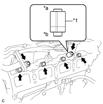
INSTALL IGNITION COIL ASSEMBLY
-
Install the 4 ignition coil assemblies with the 4 bolts.
- Torque:
- 10 N*m { 102 kgf*cm, 7 ft.*lbf }
Tech Tips
Perform "Inspection After Repair" after replacing the ignition coil assembly Click here.
-
Connect the 4 ignition coil assembly connectors.
-
-
INSTALL SENSOR WIRE
-
Install the sensor wire with the bolt.
- Torque:
- 21 N*m { 214 kgf*cm, 15 ft.*lbf }
-
Connect the knock control sensor connector.
-
-
INSTALL FUEL DELIVERY PIPE SUB-ASSEMBLY
-
Text in Illustration *1 Fuel Delivery Spacer *a Fuel Delivery Pipe Side *b Cylinder Head Side Install 4 new injector vibration insulators to the cylinder head.
-
Install the 2 fuel delivery spacers onto the cylinder head.
Tech Tips
Install the fuel delivery spacer so that the longer protrusion is on the cylinder head side.
-
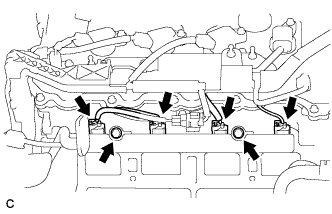
Install the fuel delivery pipe sub-assembly with the 4 fuel injector assemblies and install the 2 bolts.
- Torque:
- 21 N*m { 214 kgf*cm, 15 ft.*lbf }
Note
-
Do not drop the fuel injectors when installing the fuel delivery pipe sub-assembly.
-
Check that the fuel injector assemblies rotate smoothly after installing the fuel delivery pipe sub-assembly.
-
Connect the 4 fuel injector connectors.
-
-
INSTALL INTAKE MANIFOLD
-
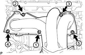
Temporarily install the intake manifold with the 6 bolts.
-
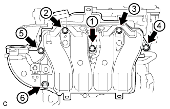
Tighten the 6 bolts in the order shown in the illustration.
- Torque:
- 21 N*m { 214 kgf*cm, 15 ft.*lbf }
-
Connect the 6 wire harness clamps.
-
Connect the heated oxygen sensor connector.
-
Connect the No. 2 ventilation hose.
-
-
INSTALL NO. 1 COMPRESSOR MOUNTING BRACKET
-
Install the No. 1 compressor mounting bracket with the 4 bolts.
- Torque:
- 25 N*m { 255 kgf*cm, 18 ft.*lbf }
-
-
INSTALL WATER INLET HOUSING
-
Using an E5 "TORX" socket, install the stud bolt to the water inlet housing.
- Torque:
- 8.0 N*m { 82 kgf*cm, 71 in.*lbf }
-
Using an E8 "TORX" socket, install the stud bolt to the cylinder block.
- Torque:
- 15 N*m { 153 kgf*cm, 11 ft.*lbf }
-
Install a new gasket.
-
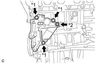
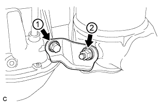
Text in Illustration *1 Bolt *2 Nut Install the water inlet housing with the 3 bolts and nut.
- Torque:
- 43 N*m { 438 kgf*cm, 32 ft.*lbf }
-
Install the harness clamp bracket to the water inlet housing with the bolt.
- Torque:
- 10 N*m { 102 kgf*cm, 7 ft.*lbf }
-
Install the harness clamp bracket to the cylinder block with the bolt.
- Torque:
- 8.0 N*m { 82 kgf*cm, 71 in.*lbf }
-
-
INSTALL WATER INLET SUB-ASSEMBLY
-
Install a new gasket and the water inlet sub-assembly with the 2 bolts.
- Torque:
- 10 N*m { 102 kgf*cm, 7 ft.*lbf }
-
-
INSTALL ENGINE WATER PUMP ASSEMBLY
-
Install a new gasket and the engine water pump assembly with the 5 bolts.
- Torque:
- 21 N*m { 214 kgf*cm, 15 ft.*lbf }
-
Connect the connector to the engine water pump assembly.
-
Connect the clamp.
-
-
INSTALL COMPRESSOR WITH MOTOR ASSEMBLY
-
Using an E8 "TORX" socket, and install the 2 stud bolts.
- Torque:
- 10 N*m { 102 kgf*cm, 7 ft.*lbf }
-
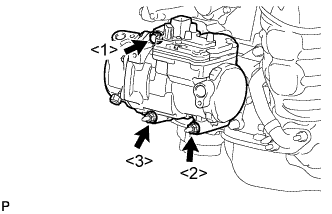
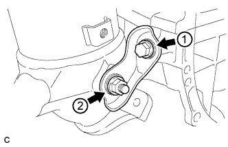
Install the compressor with motor assembly with the bolt and 2 nuts.
Tech Tips
Tighten the 2 bolts and nut in the order shown in the illustration.
- Torque:
- 25 N*m { 250 kgf*cm, 18 ft.*lbf }
-
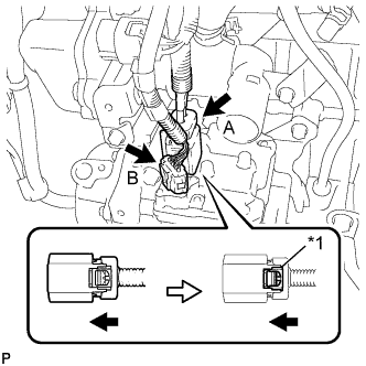
Text in Illustration *1 Green-colored Lock Connect connector A and lock the green-colored lock as shown in the illustration.
-
Connect connector B.
-
-
INSTALL NO. 1 EGR PIPE
-
Install the No. 1 EGR pipe with the 2 bolts.
- Torque:
- 21 N*m { 214 kgf*cm, 15 ft.*lbf }
-
-
INSTALL EGR COOLER ASSEMBLY
-
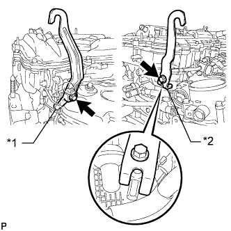
Install the No. 4 water by-pass hose, No. 6 water by-pass hose and No. 1 water by-pass pipe with the 2 clamps.
-
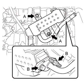
Temporarily install 2 new gaskets and the EGR cooler assembly with the bolt (A) and nut (A).
-
Temporarily install the bolt (B) and nut (B).
-
Tighten the 3 bolts and nut.
- Torque:
- 21 N*m { 214 kgf*cm, 15 ft.*lbf }
Note
Make sure that all installation surfaces of the EGR cooler assembly are in even contact when tightening the bolts and nuts.
-
-
INSTALL EXHAUST MANIFOLD CONVERTER SUB-ASSEMBLY
-
Set a new gasket to the cylinder head sub-assembly.
-
Temporarily install the exhaust manifold converter sub-assembly with the 5 nuts.
-
Temporarily install the No. 2 manifold stay and manifold stay with the 2 bolts and 2 nuts.
-
Tighten the 5 nuts in the order shown in the illustration.
- Torque:
- 35 N*m { 357 kgf*cm, 26 ft.*lbf }
-
-
INSTALL MANIFOLD STAY
-
Tighten the bolt and nut in the order shown in the illustration.
- Torque:
- 43 N*m { 438 kgf*cm, 32 ft.*lbf }
-
-
INSTALL NO. 2 MANIFOLD STAY
-
Tighten the bolt and nut in the order shown in the illustration.
- Torque:
- 43 N*m { 438 kgf*cm, 32 ft.*lbf }
-
-
INSTALL NO. 2 EGR PIPE
-
Install 2 new gaskets to the No. 2 EGR pipe.
-
Install the No. 2 EGR pipe with the 2 bolts and 2 nuts.
- Torque:
- 36 N*m { 367 kgf*cm, 26 ft.*lbf }
-
-
INSTALL NO. 1 EXHAUST MANIFOLD HEAT INSULATOR
-
Install the No. 1 exhaust manifold heat insulator with the 4 bolts.
- Torque:
- 12 N*m { 122 kgf*cm, 9 ft.*lbf }
-
-
INSTALL THROTTLE WITH MOTOR BODY ASSEMBLY
-
Install a new gasket to the intake manifold.
-
Install the throttle with motor body assembly with the 4 bolts.
- Torque:
- 10 N*m { 102 kgf*cm, 7 ft.*lbf }
-
Connect the throttle body connector.
-
Connect the 2 water by-pass hoses to the throttle with motor body assembly.
-
Connect the 2 hoses.
-
-
INSTALL NO. 1 WATER BY-PASS HOSE
-
Connect the No. 1 water by-pass hose with the clamp.
-
-
INSTALL ENGINE OIL LEVEL DIPSTICK GUIDE
-
Apply a light coat of engine oil to a new O-ring.
-
Install the O-ring to the engine oil level dipstick guide.
-
Install the engine oil level dipstick guide with the bolt.
- Torque:
- 10 N*m { 102 kgf*cm, 7 ft.*lbf }
-
Install the engine oil level dipstick.
-
-
INSTALL ENGINE HANGERS
-
Install the 2 engine hangers with the 4 bolts as shown in the illustration.
Part No. Item Part No. No. 1 Engine Hanger 12281-36020 No. 2 Engine Hanger 12282-36021 Bolt 91552-81040 or 91552-81025 - Torque:
- 43 N*m { 438 kgf*cm, 32 ft.*lbf }
-
Attach an engine sling device and hang the engine with a chain block.
-