BATTERY SMART UNIT REMOVAL

-
PRECAUTION
-
REMOVE SERVICE PLUG GRIP
-
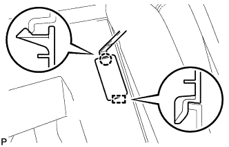
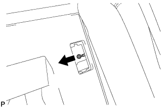
REMOVE CONNECTOR COVER ASSEMBLY
CAUTION:
Wear insulated gloves.
-
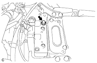
Remove the bolt and connector cover assembly.
Note
-
Make sure to pull the connector cover assembly straight up, as a connector is connected to the bottom of the cover.
-
Do not allow any foreign matter or water to enter the inverter with converter assembly.
-
-
-
CHECK TERMINAL VOLTAGE
CAUTION:
Wear insulated gloves.
Note
Do not allow any foreign matter or water to enter the inverter with converter assembly.
-
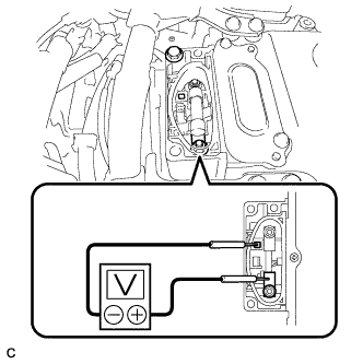
Using a voltmeter, measure the voltage between the terminals of the 2 phase connectors.
Standard voltage 0 V Tech Tips
Use a measuring range of DC 750 V or more on the voltmeter.
-
-
INSTALL CONNECTOR COVER ASSEMBLY
CAUTION:
Wear insulated gloves.
Note
-
Make sure that the interlock is fully engaged.
-
Do not allow any foreign matter or water to enter the inverter with converter assembly.
-
Install the connector cover assembly with the 2 bolts.
- Torque:
- 8.0 N*m { 82 kgf*cm, 71 in.*lbf }
-
-
REMOVE REAR SEAT CUSHION ASSEMBLY
-
Disengage the hook of the seat cushion from the vehicle body as shown in the illustration.
Note
Follow the instructions below carefully as the cushion frame can be deformed easily.
-
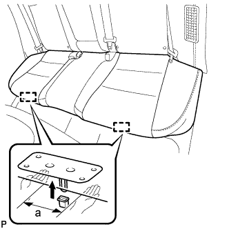
Choose a hook to disengage first. Place your hands near the hook as shown in the illustration. Then lift the seat cushion to disengage the hook.
Standard Measurement a 100 mm (3.94 in.) or less -
Repeat the step above for the other hook.
-
-
Remove the rear seat cushion assembly.
-
-
REMOVE REAR SEAT CUSHION LOCK HOOK
-
Disengage the claw and remove the rear seat cushion lock hook.
Note
Rear seat cushion lock hooks must not be reused.
Tech Tips
Use the same procedure for the RH side and the LH side.
-
-
SEPARATE REAR SEATBACK ASSEMBLY
-
Fold down the rear seatback assembly RH.
-
Using a moulding remover, disengage the claw and guide, and remove the No. 2 room partition cover.
-
Disconnect the rear seat outer belt from the rear seat center shoulder belt guide.
-
Pull the cable in the direction shown in the illustration to release the rear seatback lock and then fold the rear seatback assembly LH forward.
-
-
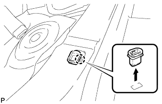
REMOVE REAR SIDE SEATBACK ASSEMBLY LH
-
Disconnect the rear seat outer belt from the rear seat shoulder belt guide LH.
-
Disconnect the connector.
-
Remove the 2 bolts.
-
Disengage the hook and remove the rear side seatback assembly LH.
-
-
REMOVE NO. 1 HYBRID BATTERY INTAKE DUCT
-
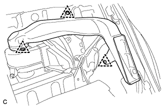
Remove the 3 clips and No. 1 hybrid battery intake duct.
-
-
REMOVE NO. 2 HYBRID VEHICLE BATTERY UPPER COVER BRACKET
-
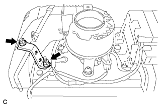
Remove the 2 nuts and No. 2 hybrid vehicle battery upper cover bracket.
-
-
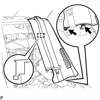
SEPARATE NO. 2 HYBRID BATTERY INTAKE DUCT
-
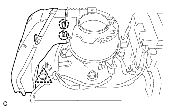
Remove the clip.
-
Disengage the 2 claws and separate the No. 2 hybrid battery intake duct.
-
-
REMOVE BATTERY COOLING BLOWER ASSEMBLY
Note
-
Be sure not to touch the fan part of the battery cooling blower assembly.
-
Do not lift the battery cooling blower assembly using the wire harness.
-
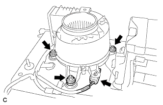
Disconnect the connector from the battery cooling blower assembly.
-
Remove the 3 nuts and battery cooling blower assembly.
-
-
REMOVE BATTERY SMART UNIT
CAUTION:
Wear insulated gloves.
-
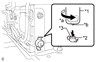
Text in Illustration *1 Service Plug Grip *2 Battery Cover Lock Striker *3 Button *a Turn *b Projection Using the service plug grip, remove the battery cover lock striker.
Tech Tips
Insert the projection part of the service plug grip, and turn the button of the battery cover lock striker counterclockwise, and release the lock.
-
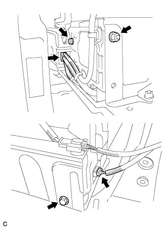
Disconnect the 2 connectors.
-
Remove the 2 bolts, nut and No. 2 hybrid vehicle battery shield panel.
-
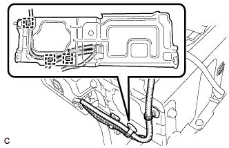
Disconnect the 3 wire harness clamps.
-
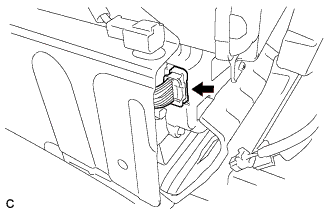
Disconnect the connector.
Note
Insulate the removed terminals with insulating tape.
-
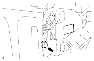
Remove the bolt.
-
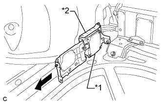
Text in Illustration *1 Battery Smart Unit *2 No. 2 Hybrid Vehicle Battery Shield Panel Remove the battery smart unit together with the No. 2 hybrid vehicle battery shield panel toward the rear of the vehicle.
Tech Tips
When removing the battery smart unit and No. 2 hybrid vehicle battery shield panel from the vehicle, they can only be removed together.
-