HYBRID CONTROL SYSTEM, Diagnostic DTC:P0C76-523

| DTC Code | DTC Name |
|---|---|
| P0C76-523 | Hybrid Battery System Discharge Time Too Long |
DESCRIPTION
Refer to the description for DTC P0A78-266 Click here.
| DTC No. | INF Code | DTC Detection Condition | Trouble Area |
|---|---|---|---|
| P0C76 | 523 | Inverter voltage (VH) sensor offset malfunction |
|
Tech Tips
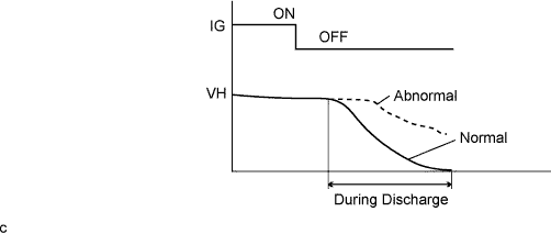
When the power switch is turned off, the MG ECU applies current to MG2 in a way that does not generate torque, in order to discharge the residual voltage in the inverter. When the hybrid system is normal, the VH value is almost 0 V after discharge. This DTC will be stored if the VH value is more than the specified value after discharge.
INSPECTION PROCEDURE
CAUTION:
-
Before inspecting the high-voltage system or disconnecting the low voltage connector of the inverter with converter assembly, take safety precautions such as wearing insulated gloves and removing the service plug grip to prevent electrical shocks. After removing the service plug grip, put it in your pocket to prevent other technicians from accidentally reconnecting it while you are working on the high-voltage system.
-
After removing the service plug grip, wait for at least 10 minutes before touching any of the high-voltage connectors or terminals. After waiting for 10 minutes, check the voltage at the terminals in the inspection point in the inverter with converter assembly. The voltage should be 0 V before beginning work Click here.
Tech Tips
Waiting for at least 10 minutes is required to discharge the high-voltage capacitor inside the inverter with converter assembly.
Note
After turning the power switch off, waiting time may be required before disconnecting the cable from the negative (-) auxiliary battery terminal. Therefore, make sure to read the disconnecting the cable from the negative (-) auxiliary battery terminal notices before proceeding with work Click here.
PROCEDURE
-
CHECK DTC OUTPUT (HYBRID CONTROL)
-
Connect the Techstream to the DLC3.
-
Turn the power switch on (IG).
-
Enter the following menus: Powertrain / Hybrid Control / Trouble Codes.
-
Check if DTCs are output.
Result Result Proceed to Only P0C76-523 is output or P0C76-523 and DTCs other than the ones in the table below are also output. A Any of the following DTCs are also output. B DTC No. Relevant Diagnosis P0A1A-151, 155, 156, 200, 658, 659, 791, 792, 793 Generator Control Module P0A1B-163, 164, 168, 193, 511, 661, 786, 794, 795, 796 Drive Motor "A" Control Module P0A1D-148 Hybrid Powertrain Control Module P0A3F-243 Drive Motor "A" Position Sensor Circuit P0A40-500 Drive Motor "A" Position Sensor Circuit Range/Performance P0A41-245 Drive Motor "A" Position Sensor Circuit Low P0A4B-253 Generator Position Sensor Circuit P0A4C-513 Generator Position Sensor Circuit Range/Performance P0A4D-255 Generator Position Sensor Circuit Low P0A78-266, 267 Drive Motor "A" Inverter Performance P0ADC-226 Hybrid Battery Positive Contactor Control Circuit High P0AE0-228 Hybrid Battery Negative Contactor Control Circuit High P0AE7-224 Hybrid Battery Precharge Contactor Control Circuit High P2511-149 ECM/PCM Power Relay Sensor Circuit Intermittent P324E-788 MG-ECU Power Relay Intermittent Circuit U0110 (all INF codes)*1 Lost Communication with Drive Motor Control Module "A" Tech Tips
-
*1: If any INF codes are output for this DTC, refer to the corresponding diagnostic procedure.
-
P0C76-523 may be output due to a malfunction which causes the DTCs in the table above to be output. In this case, first troubleshoot the output DTCs in the table above. Then, perform a reproduction test to check that no DTCs are output.
-
-
Turn the power switch off.
B 
GO TO DTC CHART (HYBRID CONTROL SYSTEM) Click here
A 
-
-
CHECK DTC OUTPUT (HYBRID CONTROL)
-
Connect the Techstream to the DLC3.
-
Turn the power switch on (IG).
-
Enter the following menus: Powertrain / Hybrid Control / Trouble Codes.
-
Check if DTCs are output.
Result Result Proceed to Any of the following DTCs are also output. A Only P0C76-523 is output or P0C76-523 and DTCs other than the ones in the table below are also output. B DTC No. Relevant Diagnosis P0A78-306 Drive Motor "A" Inverter Performance P0A7A-344 Generator Inverter Performance P0A90-251, 509 Drive Motor "A" Performance P0A92-261, 521 Hybrid Generator Performance Tech Tips
When the DTCs listed in the table above are also output, there may be a short between the HSDN (MG shut down signal) circuit and power circuit.
-
Turn the power switch off.
B
REPLACE INVERTER WITH CONVERTER ASSEMBLY Click here
A
-
-
CHECK POWER MANAGEMENT CONTROL ECU
-
Turn the power switch on (IG).
-
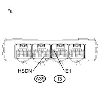
Text in Illustration *a Component with harness connected
(Power Management Control ECU)
Measure the voltage according to the value(s) in the table below.
Standard Voltage Tester Connection Switch Condition Specified Condition A39-31 (HSDN) - I3-6 (E1) Power switch on (IG) Below 4.5 V -
Turn the power switch off.
NG 
CHECK HARNESS AND CONNECTOR (POWER MANAGEMENT CONTROL ECU - INVERTER WITH CONVERTER ASSEMBLY) Click here
OK 
REPLACE INVERTER WITH CONVERTER ASSEMBLY Click here
-
-
CHECK HARNESS AND CONNECTOR (POWER MANAGEMENT CONTROL ECU - INVERTER WITH CONVERTER ASSEMBLY)
CAUTION:
Be sure to wear insulated gloves.
-
Check that the service plug grip is not installed.
Note
After removing the service plug grip, do not turn the power switch on (READY), unless instructed by the repair manual because this may cause a malfunction.
-
Disconnect connector A14 from the inverter with converter assembly.
-
Disconnect connector A39 from the power management control ECU.
-
Connect the cable to the negative (-) auxiliary battery terminal.
-
Turn the power switch on (IG).
-
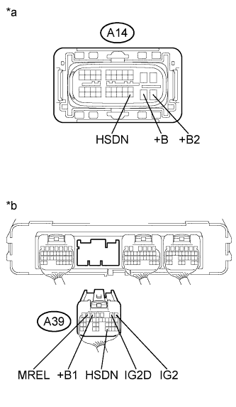
Text in Illustration *a Front view of wire harness connector
(to Inverter with Converter Assembly)
*b Rear view of wire harness connector
(to Power Management Control ECU)
Measure the voltage according to the value(s) in the table below.
Standard Voltage Tester Connection Switch Condition Specified Condition A14-40 (HSDN) or A39-31 (HSDN) - Body ground Power switch on (IG) Below 1 V Note
Turning the power switch on (IG) with the connector disconnected causes other DTCs to be stored. Clear the DTCs after performing this inspection.
-
Turn the power switch off.
-
Disconnect the cable from the negative (-) auxiliary battery terminal.
-
Measure the resistance according to the value(s) in the table below.
Standard Resistance Tester Connection Switch Condition Specified Condition A39-31 (HSDN) - A39-1 (IG2) Power switch off 10 kΩ or higher A39-31 (HSDN) - A39-2 (IG2D) Power switch off 10 kΩ or higher A39-31 (HSDN) - A39-5 (+B1) Power switch off 10 kΩ or higher A39-31 (HSDN) - A39-6 (MREL) Power switch off 10 kΩ or higher A14-40 (HSDN) - A14-30 (+B) Power switch off 10 kΩ or higher A14-40 (HSDN) - A14-31 (+B2) Power switch off 10 kΩ or higher -
Connect the inverter with converter assembly connector.
-
Connect the power management control ECU connector.
NG
REPAIR OR REPLACE HARNESS OR CONNECTOR
OK
-
-
CHECK INVERTER WITH CONVERTER ASSEMBLY
CAUTION:
Be sure to wear insulated gloves.
-
Check that the service plug grip is not installed.
Note
After removing the service plug grip, do not turn the power switch on (READY), unless instructed by the repair manual because this may cause a malfunction.
-
Disconnect connector A14 from the inverter with converter assembly.
-
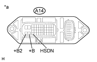
Text in Illustration *a Component without harness connected
(Inverter with Converter Assembly)
Measure the resistance according to the value(s) in the table below.
Standard Resistance Tester Connection Switch Condition Specified Condition A14-40 (HSDN) - A14-30 (+B) Power switch off 5 kΩ or higher A14-40 (HSDN) - A14-31 (+B2) Power switch off 5 kΩ or higher -
Connect the inverter with converter assembly connector.
NG
REPLACE INVERTER WITH CONVERTER ASSEMBLY Click here
OK
REPLACE POWER MANAGEMENT CONTROL ECU Click here
-