HYBRID CONTROL SYSTEM, Diagnostic DTC:P0A94-587

| DTC Code | DTC Name |
|---|---|
| P0A94-587 | DC / DC Converter Performance |
DESCRIPTION
For a description of the boost converter Click here.
The MG ECU uses a voltage sensor (VL) that is built into the boost converter to detect the high voltage before it is boosted. The ECU also uses the battery smart unit to detect HV battery voltage (VB).
Tech Tips
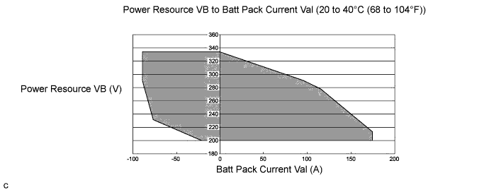
Using the Techstream, check the Data List of "Power Resource VB" and "Batt Pack Current Val". If these values are not within the below range, there is a battery smart unit malfunction.
| DTC No. | INF Code | DTC Detection Condition | Trouble Area |
|---|---|---|---|
| P0A94 | 587 | Voltages from HV battery voltage (VB) sensor and boost converter voltage (VL) sensor deviate |
|
MONITOR DESCRIPTION
The power management control ECU monitors signals of HV battery voltage (VB) and boost converter voltage (VL) sensors. When a large difference occurs between the voltages from the VB and VL sensors, the power management control ECU interprets this as a failure of either of the sensors. The power management control ECU will illuminate the MIL and set a DTC.
MONITOR STRATEGY
| Related DTCs | P0A94 (INF 587): Voltage (VB or VL) sensor deviation |
| Required sensors / components | Boost converter |
| Frequency of operation | Continuous |
| Duration | TMC's intellectual property |
| MIL operation | 1 driving cycle |
| Sequence of operation | None |
TYPICAL ENABLING CONDITIONS
| The monitor will run whenever the following DTCs are not present | TMC's intellectual property |
| Other conditions belong to TMC's intellectual property | - |
TYPICAL MALFUNCTION THRESHOLDS
| TMC's intellectual property | - |
COMPONENT OPERATING RANGE
| Power management control ECU | DTC P0A94 (INF 587) is not detected |
CONFIRMATION DRIVING PATTERN
-
Connect the Techstream to the DLC3.
-
Turn the power switch on (IG) and turn the Techstream on.
-
Clear the DTCs (even if no DTCs are stored, perform the clear DTC procedure).
-
Turn the power switch off.
-
Turn the power switch on (READY) and turn the Techstream on.
-
With the shift lever in D, depress both the accelerator pedal and brake pedal at the same time to raise the SOC to a sufficient level.
-
Move the shift lever to P, check that the engine is stopped.
-
Set the A/C for maximum cooling.
-
Leave the vehicle for a few minutes.
Tech Tips
During step 9, make sure that the engine is stopped. If the engine starts, restart from step 6.
-
Enter the following menus: Powertrain / Hybrid Control / Trouble Codes.
-
Check that permanent DTCs are cleared.
-
If the permanent DTCs are not cleared, perform the universal trip, and then check for permanent DTCs again.
Tech Tips
-
If a permanent DTC is output, the system is malfunctioning.
-
If no permanent DTC is output, the system is normal.
-
INSPECTION PROCEDURE
PROCEDURE
-
CHECK DTC OUTPUT (HYBRID CONTROL)
-
Connect the Techstream to the DLC3.
-
Turn the power switch on (IG).
-
Enter the following menus: Powertrain / Hybrid Control / Trouble Codes.
-
Check if DTCs are output.
Result Result Proceed to DTC P0A94-587 only is output. Alternatively, P0A94- 587 and any DTCs other than P0AFC-129, P0A94-442 or P0A94-585 are output. A P0A94-587 and P0AFC-129 (HV battery voltage circuit malfunction) are output. B P0A94-587 and P0A94-442 (abnormal voltage execution value) are output. C P0A94-587 and P0A94-585 (boost converter voltage (VL) sensor performance problem) are output. D -
Turn the power switch off.
B 
GO TO DTC CHART (P0AFC-129) Click here
C
REPLACE INVERTER WITH CONVERTER ASSEMBLY Click here
D
GO TO DTC CHART (P0A94-585) Click here
A 
-
-
CLEAR DTC
-
Connect the Techstream to the DLC3.
-
Turn the power switch on (IG).
-
Enter the following menus: Powertrain / Hybrid Control / Trouble Codes.
-
Read and record the DTCs and freeze frame data.
-
Clear DTCs and freeze frame data.
-
Turn the power switch off.
NEXT
-
-
CHECK DTC OUTPUT (HYBRID CONTROL)
-
Connect the Techstream to the DLC3. (*1)
-
Turn the power switch on (READY). (*2)
-
Enter the following menus: Powertrain / Hybrid Control / Data List (*3)
-
If both "Power Resource VB" and "VL-Voltage before Boosting" are less than 280 V, move the shift lever to D and depress both the accelerator pedal and brake pedal at the same time to raise them to 280 V or more. (*4)
-
Move the shift lever to P. (*5)
-
Set the air conditioning to MAX COOL and turn the headlights on. (*6)
-
Confirm that "Batt Pack Current Val" is more than 3 A. (*7)
-
Leave the vehicle for 15 seconds with the engine stopped during steps (*5) (*6) and (*7). (*8)
-
Enter the following menus: Powertrain / Hybrid Control / DTC. (*9)
-
Check if DTCs are output. (*10)
Note
If the low HV battery charge warning light comes on, Move the shift lever to P and start the engine to charge the HV battery. After the engine stops, perform steps (*1) through (*10) again.
Result Result Proceed to No DTCs are output, or DTCs other than the following are output. A P0AFC-129 (HV battery voltage circuit malfunction) is output. B P0A94-585 (boost converter voltage (VL) sensor performance problem) is output. C P3000-388 (discharge inhibition) is output. D P3004-132 (high voltage power supply line problem) is output. E -
Turn the power switch off.
B
REPLACE BATTERY SMART UNIT Click here
C
REPLACE INVERTER WITH CONVERTER ASSEMBLY Click here
D
LEAVE VEHICLE WITH SHIFT LEVER IN P, AND CHARGE HV BATTERY BY IDLING UNTIL IDLING STOPS (PERFORM STEPS (*1) THROUGH (*10))
E
REPLACE BATTERY SMART UNIT Click here
A
-
-
CHECK DTC OUTPUT (HYBRID CONTROL)
-
Turn the power switch on (READY). (*11)
-
Perform a road test that repeats full acceleration to 60 km/h (37 mph) and then braking to a complete stop three times. (*12)
-
Connect the Techstream to the DLC3. (*13)
-
Enter the following menus: Powertrain / Hybrid Control / Trouble Codes. (*14)
-
Check if DTCs are output. (*15)
Result Result Proceed to No DTCs are output, or DTCs other than the following are output. A P0AFC-129 (HV battery voltage circuit malfunction) is output. B P0A94-585 (boost converter voltage (VL) sensor performance problem) is output. C P3000-388 (discharge inhibition) is output. D P3004-132 (high voltage power supply line problem) is output. E -
Turn the power switch off.
B
REPLACE BATTERY SMART UNIT Click here
C
REPLACE INVERTER WITH CONVERTER ASSEMBLY Click here
D
LEAVE VEHICLE WITH SHIFT LEVER IN P, AND CHARGE HV BATTERY BY IDLING UNTIL IDLING STOPS (PERFORM STEPS (*11) THROUGH (*15))
E
REPLACE BATTERY SMART UNIT Click here
A
-
-
READ VALUE USING TECHSTREAM
-
Connect the Techstream to the DLC3.
-
Turn the power switch on (READY).
-
Enter the following menus: Powertrain / Hybrid Control / Data List.
-
Select "Power Resource VB", "VL-Voltage before Boosting" and "VH-Voltage after Boosting" in the Data List.
-
If both "Power Resource VB" and VL-Voltage before Boosting are less than 280 V, move the shift lever to D and depress both the accelerator pedal and brake pedal at the same time to raise them to 280 V or more.
-
Move the shift lever to P (the engine is off), and read the Data List when the vehicle is stationary.
Result Result Proceed to Both of the following are not satisfied. A Both of the following are satisfied:
-
Difference between "Power Resource VB" and "VH-Voltage after Boosting" is less than 5 V.
-
Difference between "VL-Voltage before Boosting" and "VH-Voltage after Boosting" is more than 30 V.
B Both of the following are satisfied:
-
Difference between "VH-Voltage after Boosting" and "VL-Voltage before Boosting" is more than 5 V.
-
Difference between "Power Resource VB" and "VH-Voltage after Boosting" is less than 15 V.
C -
-
Turn the power switch off.
B
REPLACE INVERTER WITH CONVERTER ASSEMBLY Click here
C
REPLACE BATTERY SMART UNIT Click here
A
-
-
CHECK FREEZE FRAME DATA (HYBRID CONTROL)
-
Connect the Techstream to the DLC3.
-
Turn the power switch on (IG).
-
Enter the following menus: Powertrain / Hybrid Control / Trouble Codes.
-
Read the freeze frame data of DTC P0A94-587.
Result Result Proceed to Both of the following are satisfied or both of the following are not satisfied. A "Power Resource VB" is less than 190 V or more than 340 V. B "VL-Voltage before Boosting" is less than 190 V or more than 340 V. C -
Turn the power switch off.
B
REPLACE BATTERY SMART UNIT Click here
C
REPLACE INVERTER WITH CONVERTER ASSEMBLY Click here
A
-
-
CHECK FREEZE FRAME DATA (HYBRID CONTROL)
-
Connect the Techstream to the DLC3.
-
Turn the power switch on (IG).
-
Enter the following menus: Powertrain / Hybrid Control / Trouble Codes.
-
Read the freeze frame data of DTC P0A94-587.
Tech Tips
In the freeze frame data, read the "Power Resource VB" and all of the "Battery Block Vol".
Result Result Proceed to Others (Freeze frame data is not stored). A Both of the following are satisfied:
-
Sum of all "Battery Block Vol" is more than ("Power Resource VB" - 45 V)
-
Sum of all "Battery Block Vol" is less than ("Power Resource VB" + 30 V)
B Neither A nor B is satisfied. C -
-
Turn the power switch off.
B
REPLACE INVERTER WITH CONVERTER ASSEMBLY Click here
C
REPLACE BATTERY SMART UNIT Click here
A
-
-
READ VALUE USING TECHSTREAM
-
Connect the Techstream to the DLC3.
-
Turn the power switch on (READY).
-
Enter the following menus: Powertrain / Hybrid Control / Data List.
-
If both "Battery Block Vol" and "VL-Voltage before Boosting" are less than 280 V, move the shift lever to D and depress both the accelerator pedal and brake pedal at the same time to raise them to 280 V or more.
-
Move the shift lever to P (the engine is off), and read the "Power Resource VB" and all of the "Battery Block Vol", when the vehicle is stationary.
Result Result Proceed to Both of the following are satisfied:
-
Sum of all "Battery Block Vol" is more than ("Power Resource VB" -45 V)
-
Sum of all "Battery Block Vol" is less than ("Power Resource VB" +30 V)
A The preceding condition is not satisfied. B -
-
Turn the power switch off.
B
REPLACE BATTERY SMART UNIT Click here
A 
REPLACE INVERTER WITH CONVERTER ASSEMBLY Click here
-