HYBRID CONTROL SYSTEM, Diagnostic DTC:P0AC0-817

| DTC Code | DTC Name |
|---|---|
| P0AC0-817 | Hybrid Battery Pack Current Sensor Circuit Range / Performance |
DESCRIPTION
-
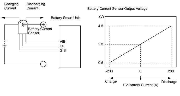
The battery current sensor, which is located in the hybrid battery junction block assembly on the positive side of the HV battery, detects the amperage that flows to and from the HV battery. The battery smart unit receives a voltage of between 0 and 5 V that is in proportion to the amperage flowing in the cable. This voltage goes into the IB terminal from the battery current sensor. A battery current sensor output voltage below 2.5 V indicates that the HV battery is being charged, and a voltage above 2.5 V indicates that the HV battery is being discharged. The power management control ECU determines the amount of either charge or discharge amperage that is being received by the HV battery based on the signals that are input to terminal IB of the battery smart unit from the battery current sensor. The power management control ECU also calculates the SOC (state of charge) of the HV battery based on the accumulated amperage.
| DTC No. | INF Code | DTC Detection Condition | Trouble Area |
|---|---|---|---|
| P0AC0 | 817 | HV battery current sensor performance problem |
|
MONITOR DESCRIPTION
The power management control ECU detects malfunctions of the battery current sensor by monitoring MG1 and MG2 torque. If the power management control ECU detects a battery current sensor malfunction, the power management control ECU will illuminate the MIL and set a DTC.
MONITOR STRATEGY
| Related DTCs | P0AC0 (INF 817): Current sensor malfunction (gain or offset) |
| Required sensors / components | Battery current sensor |
| Frequency of operation | Continuous |
| Duration | TMC's intellectual property |
| MIL operation | TMC's intellectual property |
| Sequence of operation | None |
TYPICAL ENABLING CONDITIONS
| The monitor will run whenever the following DTCs are not present | TMC's intellectual property |
| Other conditions belong to TMC's intellectual property | - |
TYPICAL MALFUNCTION THRESHOLDS
| TMC's intellectual property | - |
COMPONENT OPERATING RANGE
| Power management control ECU | DTC P0AC0 (INF 817) is not detected |
CONFIRMATION DRIVING PATTERN
-
Connect the Techstream to the DLC3.
-
Turn the power switch on (IG) and turn the Techstream on.
-
Clear the DTCs (even if no DTCs are stored, perform the clear DTC procedure).
-
Turn the power switch off.
-
Turn the power switch on (READY) and turn the Techstream on.
-
Perform the universal trip.
-
Enter the following menus: Powertrain / Hybrid Control / Trouble Codes.
-
Check that permanent DTCs are cleared.
Tech Tips
-
If a permanent DTC is output, the system is malfunctioning.
-
If no permanent DTC is output, the system is normal.
-
INSPECTION PROCEDURE
PROCEDURE
-
CHECK DTC OUTPUT (HYBRID CONTROL)
-
Connect the Techstream to the DLC3.
-
Turn the power switch on (IG).
-
Enter the following menus: Powertrain / Hybrid Control / Trouble Codes.
-
Check if DTCs are output.
Result Result Proceed to P0AC0-817 only is output. A P0AFC-123 is output. B -
Turn the power switch off.
B 
GO TO DTC CHART (P0AFC-123) Click here
A 
-
-
REPLACE HYBRID BATTERY JUNCTION BLOCK ASSEMBLY
NEXT
-
CLEAR DTC
-
Connect the Techstream to the DLC3.
-
Turn the power switch on (IG).
-
Enter the following menus: Powertrain / Hybrid Control / Trouble Codes.
-
Read and record the DTCs and freeze frame data.
-
Clear DTCs and freeze frame data.
-
Turn the power switch off.
NEXT
-
-
PERFORM ROAD TEST
NEXT
-
CHECK DTC OUTPUT (HYBRID CONTROL)
-
Connect the Techstream to the DLC3.
-
Turn the power switch on (IG).
-
Enter the following menus: Powertrain / Hybrid Control / Trouble Codes.
-
Check if DTCs are output.
Result Result Proceed to P0AC0-817 is not output. A P0AC0-817 is output again. B -
Turn the power switch off.
B
REPLACE BATTERY SMART UNIT Click here
A 
COMPLETED
-