SUB RADIATOR INSTALLATION

-
INSTALL RADIATOR ASSEMBLY
-
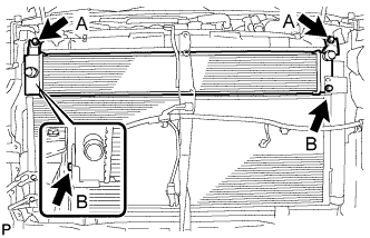
Install the radiator assembly with the 4 bolts.
- Torque:
- Bolt A
- 5.0 N*m { 51 kgf*cm, 44 in.*lbf }
- Bolt B
- 9.0 N*m { 92 kgf*cm, 80 in.*lbf }
-
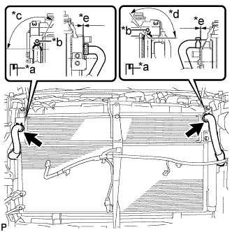
Text in Illustration *a Alignment Mark *b Rib *c 120° *d 135° *e 1 to 5 mm (0.0394 to 0.197 in.) Connect the 2 water hoses.
Note
-
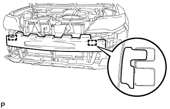
Make sure that the clip is positioned as shown in the illustration.
-
Make sure to align the alignment marks of the hoses with the ribs of the radiator assembly.
-
Do not remove the pieces of cloth or plastic bags from the pipes and disconnected hoses until installation.
-
-
-
INSTALL RADIATOR SIDE DEFLECTOR RH
-
Engage the 3 claws to install the radiator side deflector RH.
-
-
INSTALL UPPER RADIATOR SUPPORT
-
Install the 2 radiator support cushions to the radiator assembly.
-
Install the upper radiator support with the 5 bolts and connect the hood lock control cable clamp to the upper radiator support.
- Torque:
- 12 N*m { 122 kgf*cm, 9 ft.*lbf }
-
Connect the 2 connectors.
-
-
INSTALL HOOD LOCK ASSEMBLY
-
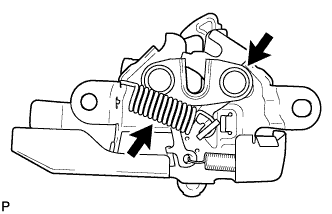
Apply MP grease to the sliding areas of the lock.
-
Connect the hood lock control cable assembly.
-
Install the hood lock assembly with the 3 bolts.
- Torque:
- 7.5 N*m { 76 kgf*cm, 66 in.*lbf }
-
w/ Engine Hood Courtesy Switch:
-
Connect the connector.
-
-
-
INSTALL RADIATOR RESERVE TANK ASSEMBLY
-
Install the radiator reserve tank with the 2 bolts.
- Torque:
- 7.0 N*m { 71 kgf*cm, 62 in.*lbf }
-
Connect the radiator reserve tank hose.
-
-
INSTALL NO. 5 INVERTER BRACKET
-
Temporarily install the No. 5 inverter bracket with the 2 bolts.
-
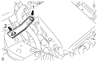
Tighten the 2 bolts in the order shown in the illustration.
- Torque:
- 10 N*m { 102 kgf*cm, 7 ft.*lbf }
-
-
INSTALL INLET AIR CLEANER ASSEMBLY
-
Install the inlet air cleaner assembly with the 2 bolts.
- Torque:
- 8.0 N*m { 82 kgf*cm, 71 in.*lbf }
-
-
INSTALL FRONT BUMPER REINFORCEMENT SUB-ASSEMBLY
-
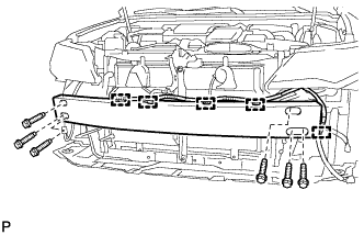
Install the front bumper reinforcement sub-assembly with the 6 bolts.
- Torque:
- 61 N*m { 622 kgf*cm, 45 ft.*lbf }
-
Engage the 5 clamps.
-
-
INSTALL FRONT BUMPER ENERGY ABSORBER
-
Engage the 2 guides to install the front bumper energy absorber.
-
-
INSTALL FRONT BUMPER ASSEMBLY
-
ADD COOLANT (for Inverter)
Note
-
Do not reuse the drained coolant because it may contain foreign objects.
-
If the vehicle is driven with air in the inverter cooling system, damage may occur and the following DTCs may be set.
DTC Code Detection Item P0A01-726 Motor Electronics Coolant Temperature Sensor Circuit Range / Performance P0A04-725 Motor Electronics Coolant Temperature Sensor Circuit Intermittent P0A08-264 DC / DC Converter Status Circuit P0A78-284 Drive Motor "A" Inverter Performance P0A78-286 Drive Motor "A" Inverter Performance P0A7A-322 Generator Inverter Performance P0A7A-324 Generator Inverter Performance P0A93-346 Inverter Cooling System Performance P0A94-553 DC / DC Converter Performance P0A94-557 DC / DC Converter Performance P0AEE-277 Motor Inverter Temperature Sensor "A" Circuit Range / Performance P0AF1-276 Drive Motor Inverter Temperature Sensor "A" Circuit Intermittent / Erratic P0BCD-315 Generator Inverter Temperature Sensor Circuit Range / Performance P0BD0-314 Generator Inverter Temperature Sensor Circuit Intermittent / Erratic P0C39-626 DC / DC Converter Temperature Sensor "A" Range / Performance P0C3C-625 DC / DC Converter Temperature Sensor "A" Intermittent / Erratic P0C3E-628 DC / DC Converter Temperature Sensor "B" Range / Performance P0C41-627 DC / DC Converter Temperature Sensor "B" Intermittent / Erratic P0C73-776 Motor Electronics Coolant Pump "A" Control Performance
-
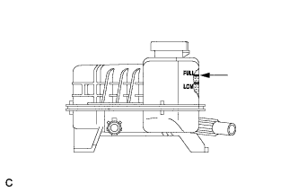
Slowly pour coolant into the reserve tank until it reaches the FULL line.
Coolant quantity 3.2 liters (3.4 US qts, 2.8 Imp. qts.) Note
To prevent foreign matter such as dust or dirt from entering the cooling system, make sure to confirm that the container used to add coolant is clean and free of foreign matter such as dust or dirt.
-
When using the Techstream:
-
Connect the Techstream to the DLC3.
-
Turn the power switch on (IG).
-
Enter the following menus: Powertrain / Hybrid Control / Active Test / Activate the Water Pump.
-
Keep the coolant at the FULL line in the reserve tank to compensate for the drop in coolant level when the air bleeds.
Standard Air bleeding from the inverter cooling system is completed when the noise made by the inverter water pump assembly becomes smaller and the circulation of coolant in the reserve tank improves. Tech Tips
-
If free spinning of the inverter water pump is detected for approximately 5 seconds, failsafe control will be activated to suspend the operation of the pump for approximately 15 seconds and resume operation for approximately 4 seconds repeatedly. Operation of the inverter water pump will return to normal if coolant is added.
-
Loud noise made by the inverter water pump assembly and poor circulation of coolant in the reserve tank indicates that there is air in the cooling system.
Tech Tips
Loud noise made by the water pump and poor circulation of coolant in the reserve tank indicates that there is air in the cooling system.
-
-
-
When not using the Techstream:
-
Turn the power switch on (READY).[*1]
-
Turn the power switch off and add coolant to the FULL line because the coolant level drops as the air bleeds.[*2]
Note
-
Be sure to turn the power switch off before adding SLLC.
-
Do not work on the components in the engine compartment while the vehicle is in the READY-on state because the engine is in intermittent operation.
-
-
Repeat steps [*1] and [*2] until air bleeding from the cooling system is completed.
Standard Air bleeding from the inverter cooling system is completed when the noise made by the inverter water pump assembly becomes smaller and the circulation of coolant in the reserve tank improves. Tech Tips
Loud noise made by the water pump and poor circulation of coolant in the reserve tank indicates that there is air in the cooling system.
-
-
After the air is completely bled from the cooling system, tighten the reserve tank cap.
-
Add coolant to the FULL line of the reserve tank.
-
-
INSPECT FOR COOLANT LEAK (for Inverter)
-
Remove the reserve tank cap.
CAUTION:
To avoid the danger of being burned, do not remove the reserve tank cap while the coolant for the inverter is still hot.
-
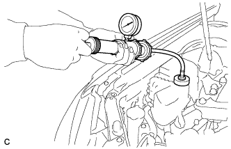
Install the radiator cap tester.
-
Pump the radiator cap tester to 122 kPa (1.2 kgf/ cm2, 17 psi), and then check that the pressure does not drop.
Tech Tips
If the pressure drops, check the hoses, radiator, water pump, inverter with converter, and hybrid vehicle transaxle assembly for leaks.
-
Reinstall the reserve tank cap.
-