HIGH INTENSITY DISCHARGE HEADLIGHT BULB INSTALLATION

-
INSTALL DISCHARGE HEADLIGHT BULB
Tech Tips
Use the same procedure for the RH side and LH side Click here.
-
INSTALL LIGHT CONTROL ECU (for LH Side)
-
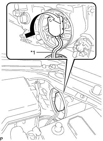
Text in Illustration *1 Red Line Turn the socket of the light control ECU in the direction indicated by the arrow shown in the illustration to connect it.
Note
-
Check that the O-ring is installed on the light control ECU.
-
Check that the O-ring is not damaged or contaminated with foreign matter. If there is any damage, replace the O-ring with a new one.
-
Do not pull the light control ECU with the socket connected.
-
-
Check that the red line on the output harness is not twisted and store the harness in the headlight assembly securely so that the output harness is not pinched.
-
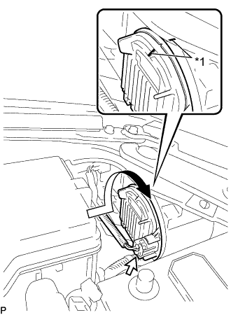
Text in Illustration *1 Lock Mark Turn the light control ECU in the direction indicated by the arrow shown in the illustration until the lock marks are aligned to install it.
Note
-
To prevent incomplete installation, make sure to fully push in and turn the light control ECU until the lock marks are aligned.
-
Do not apply excessive force using a tool.
-
-
Connect the connector.
-
-
INSTALL LIGHT CONTROL ECU (for RH Side)
-
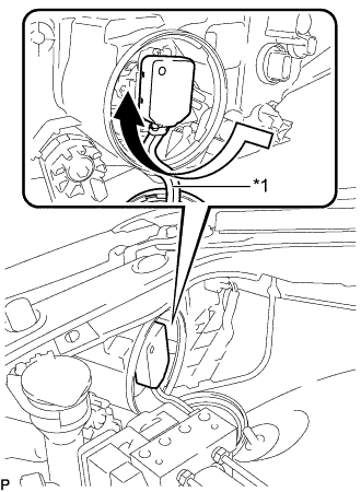
Text in Illustration *1 Red Line Turn the socket of the light control ECU in the direction indicated by the arrow shown in the illustration to connect it.
Note
-
Check that the O-ring is installed on the light control ECU.
-
Check that the O-ring is not damaged or contaminated with foreign matter. If there is any damage, replace the O-ring with a new one.
-
Do not pull the light control ECU with the socket connected.
-
-
Check that the red line on the output harness is not twisted and store the harness in the headlight assembly securely so that the output harness is not pinched.
-
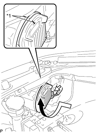
Text in Illustration *1 Lock Mark Turn the light control ECU in the direction indicated by the arrow shown in the illustration until the lock marks are aligned to install it.
Note
-
To prevent incomplete installation, make sure to fully push in and turn the light control ECU until the lock marks are aligned.
-
Do not apply excessive force using a tool.
-
-
Connect the connector.
-
-
INSTALL RADIATOR RESERVE TANK ASSEMBLY (for RH Side)
-
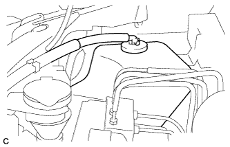
Install the radiator reserve tank assembly.
-
Install the radiator reserve tank cap assembly.
-
-
CONNECT CABLE TO NEGATIVE BATTERY TERMINAL
Note
When disconnecting the cable, some systems need to be initialized after the cable is reconnected Click here.