LIGHTING SYSTEM Parking Brake Switch Circuit
DESCRIPTION
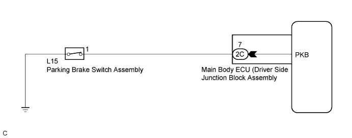
The main body ECU (driver side junction block assembly) detects the condition of the parking brake switch.
WIRING DIAGRAM
INSPECTION PROCEDURE
PROCEDURE
-
READ VALUE USING GTS
-
Connect the GTS to the DLC3.
-
Turn the ignition switch to ON.
-
Turn the GTS on.
-
Enter the following menus: Body Electrical / Main Body / Data List.
-
Read the display on the GTS.
Main Body Tester Display Measurement Item/Range Normal Condition Diagnostic Note Parking Brake SW Parking brake SW signal/ON or OFF ON: Parking brake switch on
OFF: Parking brake switch off
- OK Normal conditions listed above are displayed.
NG 
INSPECT PARKING BRAKE SWITCH ASSEMBLY Click here
OK 
PROCEED TO NEXT SUSPECTED AREA SHOWN IN PROBLEM SYMPTOMS TABLE Click here
-
-
INSPECT PARKING BRAKE SWITCH ASSEMBLY
-
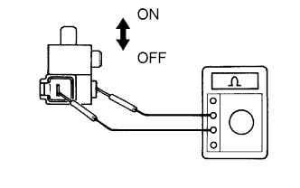
Remove the parking brake switch assembly Click here.
-
Measure the resistance according to the value(s) in the table below.
Standard Resistance Tester Connection Condition Specified Condition 1 - Switch body Shaft pushed in (OFF) 10 kΩ or higher 1 - Switch body Shaft not pushed in (ON) Below 1 Ω
NG 
REPLACE PARKING BRAKE SWITCH ASSEMBLY Click here
OK 
-
-
CHECK HARNESS AND CONNECTOR (SWITCH - MAIN BODY ECU (DRIVER SIDE JUNCTION BLOCK ASSEMBLY))
-
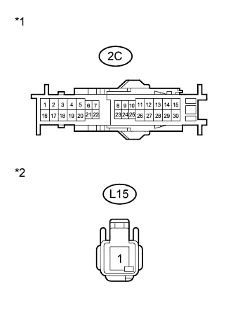
Text in Illustration *1 Front view of wire harness connector
(to Main Body ECU (Driver Side Junction Block Assembly))
*2 Front view of wire harness connector
(to Parking Brake Switch Assembly)
Disconnect the 2C main body ECU (driver side junction block assembly) connector.
-
Disconnect the L15 parking brake switch assembly connector.
-
Measure the resistance according to the value(s) in the table below.
Standard Resistance Tester Connection Condition Specified Condition 2C-7 - L15-1 Always Below 1 Ω 2C-7 - Body ground Always 10 kΩ or higher
NG
REPAIR OR REPLACE HARNESS OR CONNECTOR
OK
REPLACE MAIN BODY ECU (DRIVER SIDE JUNCTION BLOCK ASSEMBLY) Click here
-