LIGHTING SYSTEM Daytime Running Light Relay Circuit
DESCRIPTION
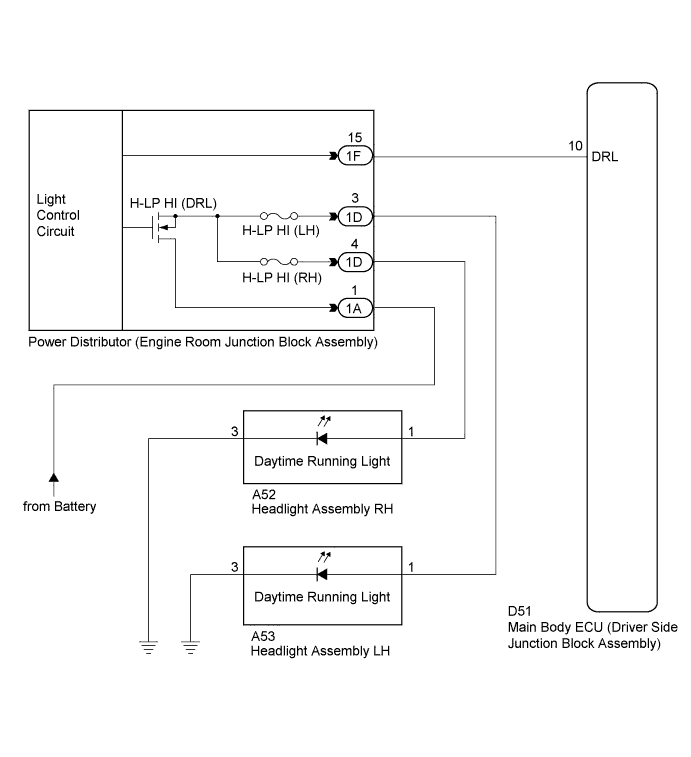
The main body ECU (driver side junction block assembly) controls the daytime running lights.
WIRING DIAGRAM
INSPECTION PROCEDURE
PROCEDURE
-
PERFORM ACTIVE TEST USING GTS
-
Connect the GTS to the DLC3.
-
Turn the ignition switch to ON.
-
Turn the GTS on.
-
Enter the following menus: Body Electrical / Main Body / Active Test.
-
Check that the relay operates.
Main Body Tester Display Test Part Control Range Diagnostic Note Daytime Running Light Daytime running light relay ON/OFF - OK Relay operates. (Daytime running lights illuminate.)
NG 
INSPECT POWER DISTRIBUTOR (ENGINE ROOM JUNCTION BLOCK ASSEMBLY) Click here
OK 
PROCEED TO NEXT SUSPECTED AREA SHOWN IN PROBLEM SYMPTOMS TABLE Click here
-
-
INSPECT POWER DISTRIBUTOR (ENGINE ROOM JUNCTION BLOCK ASSEMBLY)
-
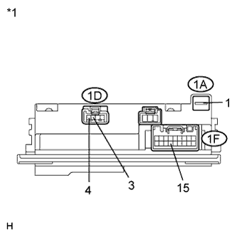
Text in Illustration *1 Component without harness connected
(Power Distributor (Engine Room Junction Block Assembly))
Remove the power distributor (engine room junction block assembly) from the engine room relay block Click here.
-
Connect a positive (+) lead from the battery to terminal 1A-1.
-
Connect a negative (-) lead from the battery to terminal 1F-15.
-
Check for pulses according to the value(s) in the table below.
Standard Tester Connection Condition Specified Condition 1D-3 - Battery negative Always Pulse generation 1D-4 - Battery negative Always Pulse generation
NG 
REPLACE POWER DISTRIBUTOR (ENGINE ROOM JUNCTION BLOCK ASSEMBLY) Click here
OK 
-
-
CHECK HARNESS AND CONNECTOR (ENGINE ROOM JUNCTION BLOCK ASSEMBLY - MAIN BODY ECU)
-
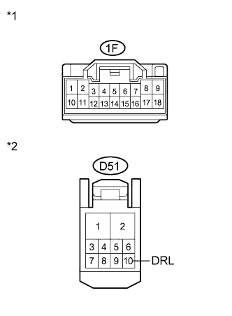
Text in Illustration *1 Front view of wire harness connector
(to Power Distributor (Engine Room Junction Block Assembly))
*2 Front view of wire harness connector
(to Main Body ECU (Driver Side Junction Block Assembly))
Disconnect the 1F power distributor (engine room junction block assembly) connector.
-
Disconnect the D51 main body ECU (driver side junction block assembly) connector.
-
Measure the resistance according to the value(s) in the table below.
Standard Resistance Tester Connection Condition Specified Condition 1F-15 - D51-10 (DRL) Always Below 1 Ω D51-10 (DRL) - Body ground Always 10 kΩ or higher
NG
REPAIR OR REPLACE HARNESS OR CONNECTOR
OK
REPLACE MAIN BODY ECU (DRIVER SIDE JUNCTION BLOCK ASSEMBLY) Click here
-