LIGHTING SYSTEM Headlight Solenoid Circuit
DESCRIPTION
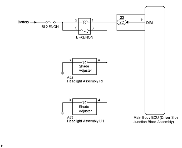
When the main body ECU receives a high beam turn on signal, the main body ECU activates the bi-function by controlling the BI-XENON relay. The bi-function increases the upper illumination area of the discharge bulb (low beam) by moving a shade using a solenoid built into the headlight unit.
WIRING DIAGRAM
INSPECTION PROCEDURE
Note
Inspect the fuses for circuits related to this system before performing the following inspection procedure.
PROCEDURE
-
CHECK OPERATION (LOW BEAM HEADLIGHTS)
-
Check the operation of the low beam headlights.
OK Low beam headlights operate normally.
NG 
GO TO PROBLEM SYMPTOMS TABLE Click here
OK 
-
-
PERFORM ACTIVE TEST USING GTS
-
Connect the GTS to the DLC3.
-
Turn the ignition switch to ON.
-
Turn the GTS on.
-
Enter the following menus: Body Electrical / Main Body / Active Test.
-
Check that the high beam headlights illuminate.
Main Body Tester Display Test Part Control Range Diagnostic Note Head Light Hi High beam headlight relay ON/OFF - OK High beam headlights illuminate.
NG 
INSPECT BI-XENON RELAY (BI-XENON) Click here
OK 
PROCEED TO NEXT SUSPECTED AREA SHOWN IN PROBLEM SYMPTOMS TABLE Click here
-
-
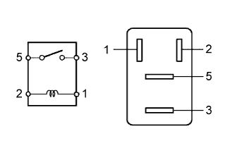
INSPECT BI-XENON RELAY (BI-XENON)
-
Remove the BI-XENON relay from the power distributor (engine room junction block assembly).
-
Measure the resistance according to the value(s) in the table below.
Standard Resistance Tester Connection Condition Specified Condition 3 - 5 Battery voltage applied to terminals 1 and 2 Below 1 Ω 3 - 5 Battery voltage not applied between terminals 10 kΩ or higher
NG
REPLACE BI-XENON RELAY
OK
-
-
CHECK HARNESS AND CONNECTOR (BATTERY - BI-XENON RELAY)
-
Measure the voltage according to the value(s) in the table below.
Standard Voltage Tester Connection Condition Specified Condition Relay terminal 2 - Body ground Always 11 to 14 V Relay terminal 5 - Body ground Always 11 to 14 V
NG
REPAIR OR REPLACE HARNESS OR CONNECTOR
OK
-
-
CHECK HARNESS AND CONNECTOR (BI-XENON RELAY - HEADLIGHT ASSEMBLY)
-
Disconnect the A53 headlight assembly LH connector.
-
Disconnect the A52 headlight assembly RH connector.
-
Measure the resistance according to the value(s) in the table below.
Standard Resistance Tester Connection Condition Specified Condition Relay terminal 3 - A53-4 Always Below 1 Ω Relay terminal 3 - A52-4 Always Below 1 Ω Relay terminal 3 - Body ground Always 10 kΩ or higher
NG
REPAIR OR REPLACE HARNESS OR CONNECTOR
OK
-
-
CHECK HARNESS AND CONNECTOR (BI-XENON RELAY - DRIVER SIDE JUNCTION BLOCK)
-
Disconnect the 2C main body ECU (driver side junction block assembly) connector.
-
Measure the resistance according to the value(s) in the table below.
Standard Resistance Tester Connection Condition Specified Condition Relay terminal 1 - 2C-23 Always Below 1 Ω 2C-23 - Body ground Always 10 kΩ or higher
NG
REPAIR OR REPLACE HARNESS OR CONNECTOR
OK
REPLACE MAIN BODY ECU (DRIVER SIDE JUNCTION BLOCK ASSEMBLY) Click here
-