LIGHTING SYSTEM, Diagnostic DTC:B124D

| DTC Code | DTC Name |
|---|---|
| B124D | Lost Communication with AFS LIN |
DESCRIPTION
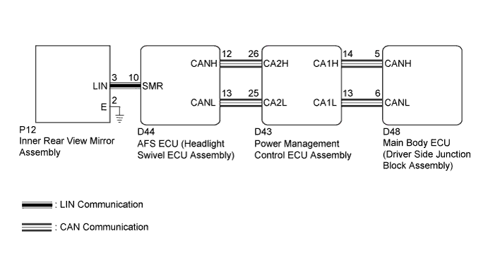
The DTC is stored when the main body ECU (driver side junction block assembly) detects malfunctions in the LIN communication system.
| DTC No. | DTC Detection Condition | Trouble Area |
|---|---|---|
| B124D | Malfunction in LIN communication system |
|
WIRING DIAGRAM
INSPECTION PROCEDURE
Note
First perform the communication function inspections in How to Proceed with Troubleshooting to confirm that there are no CAN communication malfunctions before troubleshooting this symptom.
PROCEDURE
-
CHECK FOR DTC
-
Clear the DTCs Click here.
-
Check for DTCs Click here.
OK DTC B124D is not output.
NG 
CHECK HARNESS AND CONNECTOR (AFS ECU - INNER REAR VIEW MIRROR ASSEMBLY) Click here
OK 
USE SIMULATION METHOD TO CHECK Click here
-
-
CHECK HARNESS AND CONNECTOR (AFS ECU - INNER REAR VIEW MIRROR ASSEMBLY)
-
Disconnect the D44 AFS ECU (headlight swivel ECU assembly) connector.
-
Disconnect the P12 inner rear view mirror assembly connector.
-
Measure the resistance according to the value(s) in the table below.
Standard Resistance Tester Connection Condition Specified Condition D44-10 (SMR) - P12-3 (LIN) Always Below 1 Ω P12-3 (LIN) - Body ground Always 10 kΩ or higher
NG 
REPAIR OR REPLACE HARNESS OR CONNECTOR
OK 
-
-
INSPECT AFS ECU (HEADLIGHT SWIVEL ECU ASSEMBLY)
-
Reconnect the D44 AFS ECU (headlight swivel ECU assembly) connector.
-
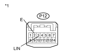
Connect an oscilloscope to the P12 inner rear view mirror assembly connector.
-
Text in Illustration *1 Front view of wire harness connector
(to Inner Rear View Mirror Assembly)
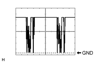
Check the waveform.
OK Tester Connection Tool Setting Condition Specified Condition P12-3 (LIN) - P12-2 (E) 2 V/DIV., 20 ms./DIV. Ignition switch ON Correct waveform is as shown
NG
REPLACE AFS ECU (HEADLIGHT SWIVEL ECU ASSEMBLY) Click here
OK
REPLACE INNER REAR VIEW MIRROR ASSEMBLY Click here
-