LIGHTING SYSTEM TERMINALS OF ECU

-
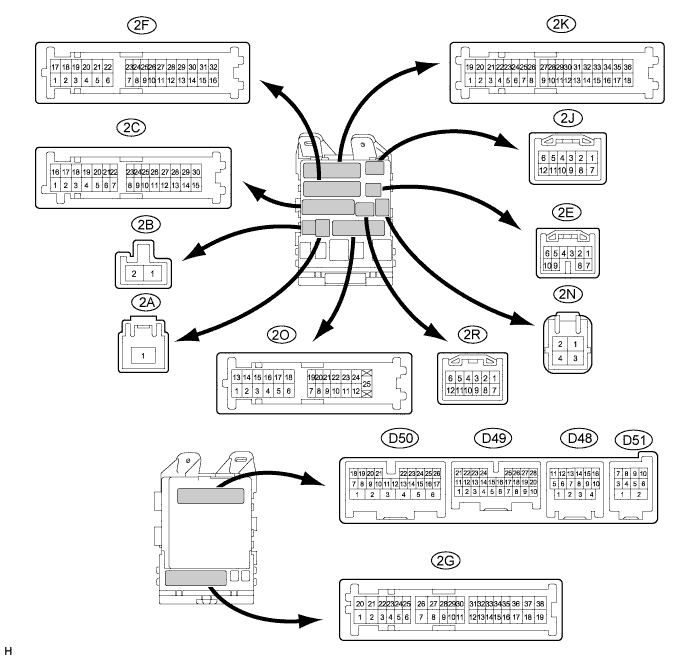
CHECK MAIN BODY ECU (DRIVER SIDE JUNCTION BLOCK ASSEMBLY)
-
Disconnect the 2A and 2F main body ECU (driver side junction block assembly) connectors.
-
Measure the voltage and resistance according to the value(s) in the table below.
Standard Voltage Terminal No. (Symbol) Wiring Color Terminal Description Condition Specified Condition 2A-1 - Body ground B - Body ground Battery power supply Always 11 to 14 V Standard Resistance Terminal No. (Symbol) Wiring Color Terminal Description Condition Specified Condition 2F-16 - Body ground W-B - Body ground Ground Always Below 1 Ω If the result is not as specified, there may be a malfunction on the wire harness side.
-
Reconnect the 2A and 2F main body ECU (driver side junction block assembly) connectors.
-
Measure the voltage and resistance according to the value(s) in the table below.
Standard Resistance Terminal No. (Symbol) Wiring Color Terminal Description Condition Specified Condition D49-18 (CLTE) - Body ground Y - Body ground Automatic light control ground Always Below 1 Ω Standard Voltage Terminal No. (Symbol) Wiring Color Terminal Description Condition Specified Condition 2C-7 (PKB) - Body ground G - Body ground Parking brake switch input Parking brake switch on Below 1 V Parking brake switch off Pulse generation 2C-23 (DIM) - Body ground GR - Body ground High beam headlight drive output Dimmer switch in high or high flash position Below 1 V Dimmer switch in low position Pulse generation 2F-5 (LSR) - Body ground Y - Body ground Rear door unlock detection switch LH or RH input Rear door LH and RH locked Pulse generation Rear door LH or RH unlocked Below 1 V 2G-35 (HRLY) - Body ground GR - Body ground Headlight relay drive output Light control switch in head position Below 1 V Light control switch not in head position 11 to 14 V 2K-7 (RFOG) - Body ground B - Body ground Rear fog light switch input Fog light switch in rear position Below 1 V Fog light switch off Pulse generation 2N-2 (HU) - Body ground G - Body ground Dimmer switch high position signal input Dimmer switch in high or high flash position Below 1 V Dimmer switch in low position Pulse generation 2O-5 (LSR) - Body ground BR - Body ground Rear door unlock detection switch LH or RH input Rear door LH and RH locked Pulse generation Rear door LH or RH unlocked Below 1 V 2O-19 (LCTY) - Body ground R - Body ground Rear door courtesy light switch LH input Rear door LH open Below 1 V Rear door LH closed Pulse generation D49-7 (RCTY) - Body ground GR - Body ground Rear door courtesy light switch RH input Rear door RH open Below 1 V Rear door RH closed Pulse generation D49-15 (RFGO) - Body ground R - Body ground Rear fog light relay drive output Light control switch in tail and fog light switch in rear position Below 1 V Fog light switch off 11 to 14 V D49-17 (HEAD) - Body ground V - Body ground Light control switch head position input Light control switch in head position Below 1 V Light control switch not in head position Pulse generation D49-19 (CLTS) - Body ground V - Body ground Automatic light control sensor signal input Ignition switch off Below 1 V Automatic light control system operates Pulse generation
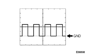
(See waveform 1)
D49-20 (CLTB) - Body ground GR - Body ground Automatic light control sensor power supply output Ignition switch off Below 1 V Ignition switch ON and light control switch in AUTO position 11 to 14 V D49-21 (PCTY) - Body ground V - Body ground Front passenger side door courtesy light switch input Front passenger side door open Below 1 V Front passenger side door closed Pulse generation D49-25 (BCTY) - Body ground GR - Body ground Back door courtesy switch input Back door open Below 1 V Back door closed 11 to 14 V D49-27 (LSWP) - Body ground P - Body ground Front passenger side door unlock detection switch input Front passenger side door locked Pulse generation Front passenger side door unlocked Below 1 V D49-28 (FFOG) - Body ground R - Body ground Front fog light switch input Fog light switch in front position Below 1 V Fog light switch off Pulse generation D50-4 (FFGO) - Body ground GR - Body ground Front fog light relay drive output Light control switch in head position and fog light switch in front position Below 1 V Fog light switch off 11 to 14 V D50-9 (LSWD) - Body ground P - Body ground Driver side door unlock detection switch input Driver side door locked Pulse generation Driver side door unlocked Below 1 V D50-13 (HF) - Body ground SB - Body ground Dimmer switch high flash position signal input Dimmer switch in high flash position Below 1 V Dimmer switch not in high flash position Pulse generation D50-21 (A) - Body ground BR - Body ground Light control switch AUTO position signal input Light control switch in AUTO position Below 1 V Light control switch not in AUTO position Pulse generation D50-23 (TAIL) - Body ground R - Body ground Light control switch tail position signal input Light control switch in tail or head position Below 1 V Light control switch in neither tail nor head position Pulse generation D50-24 (DCTY) - Body ground V - Body ground Driver side door courtesy light switch input Driver side door open Below 1 V Driver side door closed Pulse generation D51-10 (DRL) - Body ground G - Body ground Daytime running light system drive output Daytime running light system operating Below 1 V Daytime running light system not operating 11 to 14 V If the result is not as specified, the main body ECU (Driver side junction block assembly) may have a malfunction.
-

Waveform 1
Item Content Tool setting 5 V/DIV., 5 ms./DIV. Tech Tips
If the ambient light becomes brighter, width A becomes narrower.
-
-
-
CHECK HEADLIGHT LEVELING ECU ASSEMBLY
-
Disconnect the A40 headlight leveling ECU assembly connector.

-
Measure the voltage and resistance between the specified terminals of the wire harness side connectors and body ground.
Standard Voltage Terminal No. (Symbol) Wiring Color Terminal Description Condition Specified Condition A40-1 (IG) - Body ground L - Body ground IG power supply Ignition switch off Below 1 V Ignition switch ON 11 to 14 V Standard Resistance Terminal No. (Symbol) Wiring Color Terminal Description Condition Specified Condition A40-9 (E1) - Body ground W-B - Body ground Ground Always Below 1 Ω If the result is not as specified, there may be a malfunction on the wire harness side.
-
Reconnect the A40 headlight leveling ECU assembly connector.
-
Measure the resistance and voltage according to the value(s) in the table below.
Standard Resistance Terminal No. (Symbol) Wiring Color Terminal Description Condition Specified Condition A40-21 (SGR) - Body ground LG - Body ground Rear height control sensor ground Always Below 1 Ω A40-23 (RH-) - Body ground Y - Body ground Leveling motor RH ground Always Below 1 Ω A40-24 (LH-) - Body ground R - Body ground Leveling motor LH ground Always Below 1 Ω Standard Voltage Terminal No. (Symbol) Wiring Color Terminal Description Condition Specified Condition A40-3 (B2) - Body ground LG - Body ground Low beam headlight signal input Low beam headlights on Below 1.5 V Low beam headlights off Above 5 V A40-6 (WNG) - Body ground BR - Body ground Indicator light drive output Indicator light on 11 to 14 V Indicator light off Below 1 V A40-10 (RH+) - Body ground R - Body ground Leveling motor RH power supply Ignition switch off Below 1 V Ignition switch ON 10 to 16 V A40-11 (LH+) - Body ground P - Body ground Leveling motor LH power supply Ignition switch off Below 1 V Ignition switch ON 10 to 16 V A40-12 (SBR) - Body ground BR - Body ground Rear height control sensor power supply Ignition switch off Below 1 V Ignition switch ON 4.75 to 5.25 V A40-15 (PRST) - Body ground Y - Body ground Initialization signal input Terminal LVL and terminal GND of DLC3 connected Below 1 V Terminal LVL and terminal GND of DLC3 not connected Approx. 5 V A40-16 (SPDR) - Body ground GR - Body ground Vehicle speed signal input Vehicle is driven at approx. 20 km/h (12mph) Pulse generation
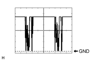
(See waveform 1)
A40-17 (RHT) - Body ground G - Body ground Leveling motor RH operation signal input With low beam headlights on, vehicle height not changed Below 1 V With low beam headlights on, change vehicle height and keep for more than 3 seconds. 1.0 to 14.4 V A40-18 (LHT) - Body ground V - Body ground Leveling motor LH operation signal input With low beam headlights on, vehicle height not changed Below 1 V With low beam headlights on, change vehicle height and keep for more than 3 seconds. 1.0 to 14.4 V A40-19 (SHRL) - Body ground BE - Body ground Rear height control sensor signal input Ignition switch off Below 1 V Ignition switch ON 0.5 to 4.5 V If the result is not as specified, the headlight leveling ECU assembly may have a malfunction.
-
Waveform 1
Item Content Tool setting 2 V/DIV., 2 ms./DIV.
-
-
-
CHECK AFS ECU (HEADLIGHT SWIVEL ECU ASSEMBLY) (w/ Automatic High Beam System)
-
Disconnect the D44 AFS ECU (headlight swivel ECU assembly) connector.

-
Measure the resistance and voltage according to the value(s) in the table below.
Standard Resistance Terminal No. (Symbol) Wiring Color Terminal Description Condition Specified Condition D44-22 (E1) - Body ground B - Body ground AFS ECU (headlight swivel ECU assembly) ground Always Below 1 Ω Standard Voltage Terminal No. (Symbol) Wiring Color Terminal Description Condition Specified Condition D44-15 (IG) - Body ground G - Body ground AFS ECU (headlight swivel ECU assembly) power supply Ignition switch off Below 1 V Ignition switch ON 11 to 14 V If the result is not as specified, there may be a malfunction on the wire harness side.
-
Reconnect the D44 AFS ECU (headlight swivel ECU assembly) connector.
-
Measure the voltage according to the value(s) in the table below.
Standard Voltage Terminal No. (Symbol) Wiring Color Terminal Description Condition Specified Condition D44-7 (MPX2) - D44-22 (E1) V - B Operation check signal Ignition switch ON, terminal LVL and GND of DLC3 connected Below 1 V Ignition switch ON, terminal LVL and GND of DLC3 not connected Approx. 5 V D44-10 (SMR) - D44-22 (E1) R - B LIN communication Ignition switch off Below 1 V Ignition switch ON, inner rear view mirror connector disconnected Pulse generation
(See waveform 1)
D44-12 (CANH) - D44-22 (E1) Y - B CAN communication Ignition switch off Below 1 V Ignition switch ON Pulse generation D44-13 (CANL) - D44-22 (E1) W - B CAN communication Ignition switch off Below 1 V Ignition switch ON Pulse generation If the result is not as specified, the ECU may have a malfunction.
-
Waveform 1
Item Content Tool setting 2 V/DIV., 20 ms./DIV.
-
-
-
CHECK INNER REAR VIEW MIRROR ASSEMBLY
-
Disconnect the P12 inner rear view mirror assembly connector.

-
Measure the resistance and voltage according to the value(s) in the table below.
Standard Resistance Terminal No. (Symbol) Wiring Color Terminal Description Condition Specified Condition P12-2 (E)*1 - Body ground W-B - Body ground Inner rear view mirror assembly ground Always Below 1 Ω Standard Voltage Terminal No. (Symbol) Wiring Color Terminal Description Condition Specified Condition P12-1 (IG)*1 - Body ground Y - Body ground Inner rear view mirror assembly power supply Ignition switch off Below 1 V Ignition switch ON 11 to 14 V
-
*1: Automatic Glare-resistant EC Mirror
If the result is not as specified, there may be a malfunction on the wire harness side.
-
-
Reconnect the P12 inner rear view mirror assembly connector.
-
Measure the voltage according to the value(s) in the table below.
Standard Voltage Terminal No. (Symbol) Wiring Color Terminal Description Condition Specified Condition P12-3 (LIN)*2 - P12-2 (E) R - W-B LIN communication Ignition switch off Below 1 V Automatic high beam system operates Pulse generation
(See waveform 1)
-
*2: w/ Automatic High Beam System
If the result is not as specified, the inner rear view mirror assembly may have a malfunction.
-
Waveform 1
Item Content Tool setting 2 V/DIV., 20 ms./DIV.
-
-
-
CHECK OUTER MIRROR CONTROL ECU ASSEMBLY LH
-
Disconnect the I13 outer mirror control ECU assembly LH connector.

-
Measure the voltage according to the value(s) in the table below.
Tech Tips
Measure the values on the wire harness side with the connector disconnected.
Standard Voltage Tester Connection Wiring Color Terminal Description Condition Specified Condition I13-14 (BDR) - Body ground V - Body ground Battery power supply Always 11 to 14 V I13-6 (CPUB) - Body ground LG - Body ground Battery power supply Always 11 to 14 V I13-5 (SIG) - Body ground L - Body ground Ignition power supply Ignition switch ON 11 to 14 V If the result is not as specified, there may be a malfunction on the wire harness side.
-
Measure the resistance according to the value(s) in the table below.
Tech Tips
Measure the values on the wire harness side with the connector disconnected.
Standard Resistance Tester Connection Wiring Color Terminal Description Condition Specified Condition I13-7 (GND) - Body ground W-B - Body ground Ground Always Below 1 Ω If the result is not as specified, there may be a malfunction on the wire harness side.
-
Reconnect the I13 outer mirror control ECU assembly LH connector.
-
Measure the voltage according to the value(s) in the table below.
Standard Voltage Tester Connection Wiring Color Terminal Description Condition Specified Condition I12-2 (LP) - I12-12 (HTR-) SB - V Door mirror foot light (LH) drive output Door mirror foot light off Below 1 V Door mirror foot light on 11 to 14 V
-
-
CHECK OUTER MIRROR CONTROL ECU ASSEMBLY RH
-
Disconnect the H13 outer mirror control ECU assembly RH connector.

-
Measure the voltage according to the value(s) in the table below.
Tech Tips
Measure the values on the wire harness side with the connector disconnected.
Standard Voltage Tester Connection Wiring Color Terminal Description Condition Specified Condition H13-14 (BDR) - Body ground R - Body ground Battery power supply Always 11 to 14 V H13-6 (CPUB) - Body ground B - Body ground Battery power supply Always 11 to 14 V H13-5 (SIG) - Body ground L - Body ground Ignition power supply Ignition switch ON 11 to 14 V If the result is not as specified, there may be a malfunction on the wire harness side.
-
Measure the resistance according to the value(s) in the table below.
Tech Tips
Measure the values on the wire harness side with the connector disconnected.
Standard Resistance Tester Connection Wiring Color Terminal Description Condition Specified Condition H13-7 (GND) - Body ground W-B - Body ground Ground Always Below 1 Ω If the result is not as specified, there may be a malfunction on the wire harness side.
-
Reconnect the H13 outer mirror control ECU assembly RH connector.
-
Measure the voltage according to the value(s) in the table below.
Standard Voltage Tester Connection Wiring Color Terminal Description Condition Specified Condition H12-2 (LP) - H12-12 (HTR-) SB - V Door mirror foot light (RH) drive output Door mirror foot light off Below 1 V Door mirror foot light on 11 to 14 V
-