WIPER SWITCH INSPECTION

-
INSPECT WINDSHIELD WIPER SWITCH ASSEMBLY
-
Remove the windshield wiper switch assembly.
-
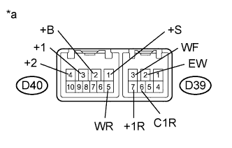
Text in Illustration *a Component without harness connected
(Windshield Wiper Switch Assembly)
Measure the resistance according to the value(s) in the table below.
Standard Resistance Front Wiper Switch Tester Connection Condition Specified Condition D40-1 (+S) - D40-3 (+1) OFF Below 1 Ω INT D40-2 (+B) - D40-3 (+1) MIST LO D40-2 (+B) - D40-4 (+2) HI Front Washer Switch Tester Connection Condition Specified Condition D39-2 (EW) - D39-3 (WF) ON Below 1 Ω OFF 10 kΩ or higher Rear Wiper Switch Tester Connection Condition Specified Condition D39-6 (C1R) - D39-2 (EW) OFF 10 kΩ or higher D39-7 (+1R) - D39-2 (EW) D39-6 (C1R) - D39-2 (EW) INT Below 1 Ω D39-7 (+1R) - D39-2 (EW) HI Below 1 Ω Rear Washer Switch Tester Connection Condition Specified Condition D40-5 (WR) - D39-2 (EW) OFF 10 kΩ or higher D39-7 (+1R) - D39-2 (EW) D40-5 (WR) - D39-2 (EW) WASH Below 1 Ω D40-5 (WR) - D39-2 (EW) ON + WASH Below 1 Ω D39-7 (+1R) - D39-2 (EW) If the result is not as specified, replace the windshield wiper switch assembly.
-
Install the windshield wiper switch assembly.
-
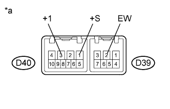
Text in Illustration *a Component with harness connected
(Windshield Wiper Switch Assembly)
Check the intermittent operation.
-
Connect a voltmeter positive (+) lead to terminal D40-3 (+1) and a negative (-) lead to terminal D39-2 (EW).
-
Turn the wiper switch to the INT position.
-
Operate the intermittent wiper and check the voltage between terminals D40-3 (+1) and D392 (EW).
OK Voltage changes as shown in the illustration. 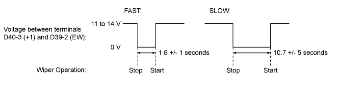
If the result is not as specified, replace the windshield wiper switch assembly.
-
-