POWER MIRROR CONTROL SYSTEM OPERATION CHECK

-
CHECK REMOTE CONTROL MIRROR FUNCTION
-
Turn the ignition switch ON.
-
With the mirror select switch set to L, check that the outer rear view mirror LH surface moves up, down, left and right normally.
-
With the mirror select switch set to R, check that the outer rear view mirror RH surface moves up, down, left and right normally.
-
-
CHECK MEMORY AND REACTIVATION FUNCTION
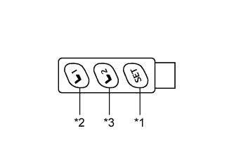
Text in Illustration *1 SET Switch *2 M1 Switch *3 M2 Switch Tech Tips
The SET, M1 and M2 seat memory switches are shown in the illustration.
-
Turn the ignition switch ON and move the shift lever to P.
-
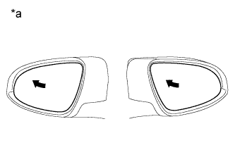
Text in Illustration *a Turn to Left Fully Check the M1 switch.
-
Using the mirror adjust switch, turn the mirror surface to the full left position.
-
Check that the buzzer sounds for 0.5 seconds and the seat position is memorized when the M1 switch is pressed within 3 seconds of the SET switch being pressed.
Note
-
The mirror surface position will be stored when the M1 switch is pressed after first pressing and holding the SET switch.
-
The mirror surface position will not be stored when the SET switch and M1 switch are pressed simultaneously.
-
The mirror surface position will not be stored when 2 or more of the memory switches are pressed simultaneously (for example, M1 and M2) after first pressing the SET switch.
-
-
Using the outer mirror switch assembly, turn the mirror surface to the full right position.
-
Press the M1 switch.
-
Check that the buzzer sounds for 0.1 seconds and the outer mirror automatically moves to the recorded full left position.
-
-
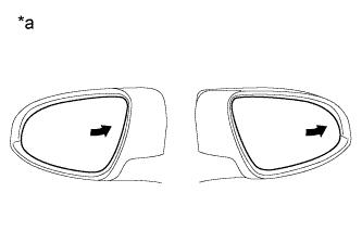
Text in Illustration *a Turn to Right Fully Check the M2 switch.
-
Using the mirror adjust switch assembly, turn the mirror surface to the full right position.
-
Check that the buzzer sounds for 0.5 seconds and the seat position is memorized when the M2 switch is pressed within 3 seconds of the SET switch being pressed.
Note
-
The mirror surface position will be stored when the M2 switch is pressed after first pressing and holding the SET switch.
-
The mirror surface position will not be stored when the SET switch and M2 switch are pressed simultaneously.
-
The mirror surface position will not be stored when 2 or more of the memory switches are pressed simultaneously (for example, M1 and M2) after first pressing the SET switch.
-
-
Using the outer mirror switch assembly, turn the mirror surface to the full left position.
-
Press the M2 switch.
-
Check that the buzzer sounds for 0.1 seconds and the outer mirror automatically moves to the recorded full right position.
-
-
-
CHECK REVERSE SHIFT-LINKED OPERATION OF MIRRORS
-
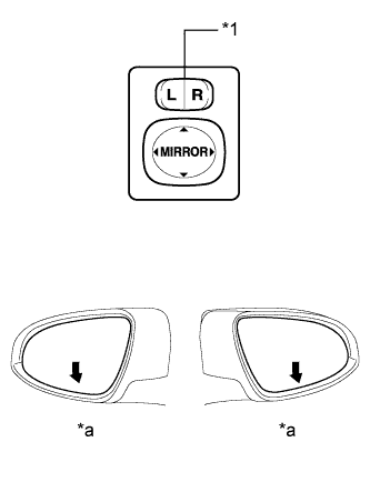
Text in Illustration *1 Mirror Select Switch *a Downward Turn the ignition switch ON.
-
Set the mirror select switch to L or R.
-
Check that the mirror surface turns downward when the shift lever is moved to R.
-
Check that the mirror surface position returns to the original position when one of the following conditions is met:
-
Shift lever is moved to any position other than R.
-
Mirror select switch is in the neutral position (off).
-
Ignition switch is turned off.
-
-
-
CHECK MEMORY CALL FUNCTION
-
Memory call function check
-
With a electrical key transmitter sub-assembly or door control transmitter assembly recognition code registered:
Perform a wireless door unlock operation and check that opening the driver side door causes the following:
-
The buzzer sounds for 0.1 seconds.
-
The front seat and outer mirror surface position automatically move to the stored positions.
Tech Tips
-
The registered electrical key transmitter sub-assembly or door control transmitter assembly recognition code is recalled automatically.
-
If the memory call function is not operated, the buzzer will not sound.
-
-
-
With the ignition switch ON and the driver door closed, press and hold the M1 or M2 switch while carrying the electrical key transmitter sub-assembly or door control transmitter assembly. The main body ECU (driver side junction block assembly) will enter electrical key transmitter sub-assembly or door control transmitter assembly recognition code registration mode to allow a key to be linked to mirror surface memory position.
Tech Tips
If the memory switch is released before entering registration mode, the memory switch will not enter registration mode.
-
When the manual door lock switch is pressed, check that the buzzer of the position control ECU and switch assembly sounds once (0.5 seconds).
-
With the ignition switch ON and the driver side door closed, press and hold the SET switch while carrying the electrical key transmitter sub-assembly or door control transmitter assembly. The main body ECU (driver side junction block assembly) will enter electrical key transmitter sub-assembly or door control transmitter assembly recognition code deletion mode.
Tech Tips
If the memory switch is released before entering deletion mode, the memory switch will not enter deletion mode.
-
When the manual door lock switch is pressed, check that the buzzer of the position control ECU and switch assembly sounds twice (0.1 seconds each time).
-
-
EMERGENCY STOP FUNCTION
-
While a memory call function is operating, check that any one of the following actions will stop the memory call operation: 1) pressing the SET, M1or M2 switch, 2) moving the shift lever to R, 3) moving the mirror surface manually, or 4) moving the mirror surface to the uppermost, lowermost, leftmost or rightmost position.
-