POWER BACK DOOR DRIVE UNIT INSTALLATION

-
INSTALL POWER BACK DOOR UNIT ASSEMBLY
-
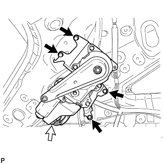
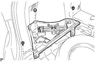
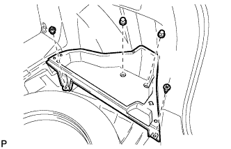
Install the power back door unit with the 4 bolts.
- Torque:
- 13 N*m { 133 kgf*cm, 10 ft.*lbf }
-
Connect the connector.
-
-
INSTALL POWER BACK DOOR ROD
-
When reusing the power back door rod:
-
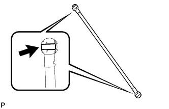
Install the 2 stop rings to the power back door rod.
-
-
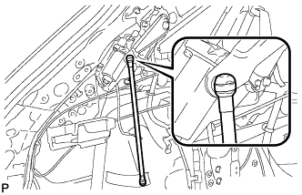
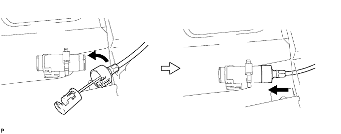
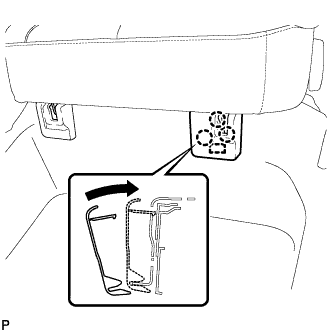
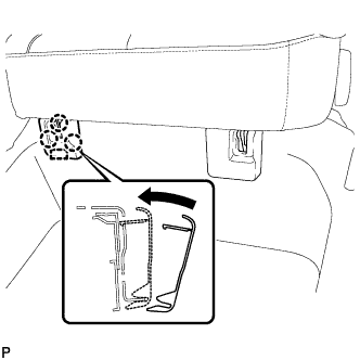
Engage the power back door rod.
-
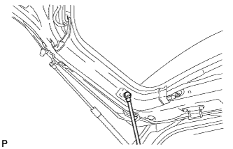
Install the power back door rod.
-
Check that the power back door rod is engaged in the ball joint and that the power back door rod cannot be pulled out.
-
-
INSTALL ROOF SIDE INNER GARNISH ASSEMBLY LH
-
Pass the floor anchor of the rear seat outer belt assembly LH through the roof side inner garnish assembly LH.
-
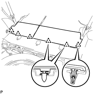
Insert the upper edge of the roof side inner garnish assembly LH into the roof headlining. Lift the lower edge of the garnish up and push it in over the 3 stud bolts while ensuring ample clearance.
Note
Do not damage the roof headlining assembly or roof side inner garnish assembly.
-
Engage the 10 clips to install the roof side inner garnish assembly LH with the bolt.
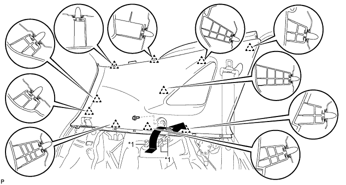
Text in Illustration *1 Stud Bolt - - -
Text in Illustration *1 Protective Tape Remove the applied protective tape.
-
w/ Rear Speaker:
-
Disconnect the connector.
-
-
-
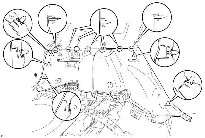
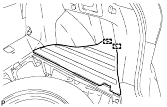
INSTALL DECK TRIM SIDE PANEL ASSEMBLY LH
-
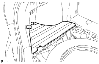
Connect the connector.
-
Engage the 7 claws and the 5 clips.
-
Install the deck trim side panel assembly LH with the bolt and clip.
-
-
CONNECT REAR SEAT OUTER BELT ASSEMBLY LH
-
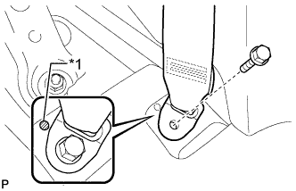
Text in Illustration *1 Protruding Part Connect the floor anchor end of the rear seat outer belt assembly and install the bolt.
- Torque:
- 42 N*m { 428 kgf*cm, 31 ft.*lbf }
Note
Do not allow the anchor part of the rear seat outer belt assembly to overlap the protruding part of the floor panel.
-
-
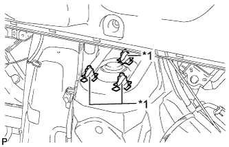
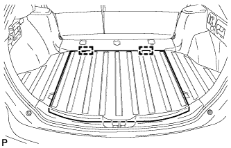
INSTALL LUGGAGE HOLD BELT STRIKER ASSEMBLY LH
-
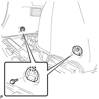
Engage the 2 guides.
-
Install the 2 luggage hold belt striker assemblies with the 2 bolts.
-
-
INSTALL RECLINING REMOTE CONTROL BEZEL LH
-
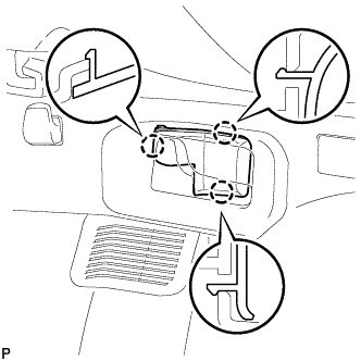
Engage the 3 claws to install the reclining remote control bezel LH.
-
-
INSTALL REAR SEAT ASSEMBLY LH
-
Place the rear seat assembly LH in the cabin.
Note
Be careful not to damage the vehicle body.
-
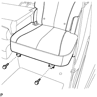
Temporarily install the 2 bolts on the front side of the seat.
-
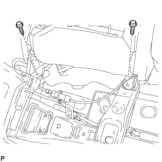
Temporarily install the 2 bolts on the rear side of the seat.
-
Install the rear seat assembly LH with the 4 bolts.
- Torque:
- 37 N*m { 377 kgf*cm, 27 ft.*lbf }
-
-
CONNECT REAR SEAT NO. 2 RECLINING CONTROL CABLE SUB-ASSEMBLY
-
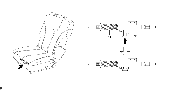
Remove the rear seat No. 2 reclining control cable from the carpet hole.
-
Connect the rear seat No. 2 reclining control cable sub-assembly as shown in the illustration.
Text in Illustration *1 Protective Tape *2 Seat Track Adjusting Handle -
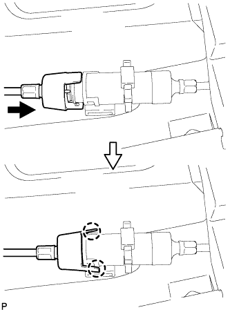
Engage the 2 claws and connect the rear seat No. 2 reclining control cable sub-assembly as shown in the illustration.
-
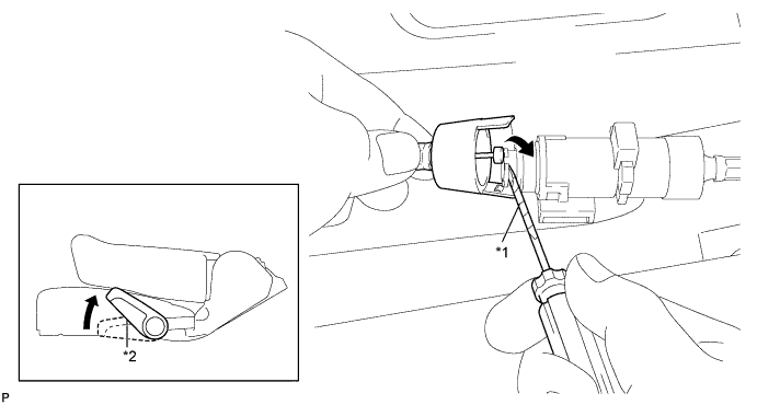
Return the seatback to the upright position.
-
Pull up the adjuster's lock piece to lock it as shown in the illustration.
Text in Illustration *1 Adjuster Spring *2 Lock Piece Note
When pressing the lock piece, make sure the adjuster's spring is not compressed.
-
-
INSTALL REAR SEAT OUTER TRACK BRACKET COVER LH
-
Engage the guide and 3 claws and install the rear seat outer track bracket cover as shown in the illustration.
-
-
INSTALL REAR SEAT INNER TRACK BRACKET COVER LH
-
Engage the guide and 3 claws and install the rear seat inner track bracket cover as shown in the illustration.
-
-
INSTALL REAR SEAT HEADREST ASSEMBLY LH
-
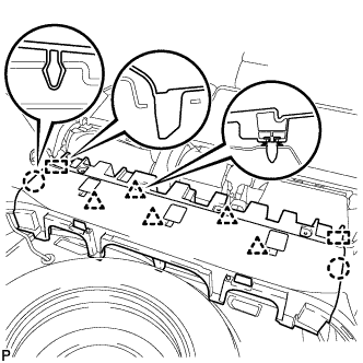
INSTALL REAR FLOOR FINISH PLATE
-
Engage the 4 clips and 2 claws to install the rear floor finish plate.
-
-
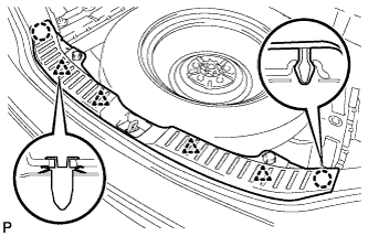
INSTALL REAR SEAT SUB FLOOR PANEL ASSEMBLY
-
Engage the 2 guides, 2 claws and 5 clips to install the rear seat sub floor panel assembly.
-
-
INSTALL NO. 1 DECK BOARD
-
Engage the 6 clips to install the No. 1 deck board.
-
-
INSTALL DECK SIDE TRIM BOX LH
-
Install the deck side trim box LH with the 3 clips.
-
-
INSTALL NO. 3 DECK BOARD SUB-ASSEMBLY
-
Engage the 2 guides to install the No. 3 deck board sub-assembly.
-
-
INSTALL DECK SIDE TRIM BOX RH
-
Install the deck side trim box RH with the 4 clips.
-
-
INSTALL NO. 2 DECK BOARD SUB-ASSEMBLY
-
Engage the 2 guides to install the No. 2 deck board sub-assembly.
-
-
INSTALL DECK BOARD ASSEMBLY
-
Engage the 2 guides to install the deck board assembly.
-
-
INSTALL TONNEAU COVER ASSEMBLY
-
Install the tonneau cover assembly.
-
-
CONNECT REAR DOOR OPENING TRIM WEATHERSTRIP LH
-
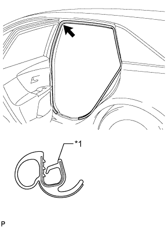
Text in Illustration *1 Alignment mark (Purple) Align the alignment mark (Purple) on the weatherstrip with the protruding portion on the body indicated by the arrow in the illustration, and install the rear door opening trim weatherstrip LH.
Note
After installation, check that the corners fit correctly.
-
-
INSTALL REAR DOOR SCUFF PLATE LH
-
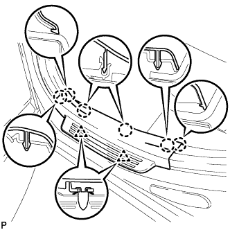
Engage the 2 clips and 6 claws to install the rear door scuff plate LH.
-
-
INITIALIZE EASY CLOSER SYSTEM
-
INITIALIZE POWER BACK DOOR SYSTEM