BACK DOOR REASSEMBLY

-
INSTALL NO. 3 ANTENNA CORD SUB-ASSEMBLY
-
Pass the washer hose through the No. 3 antenna cord sub-assembly.
-
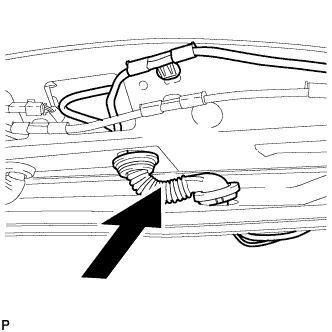
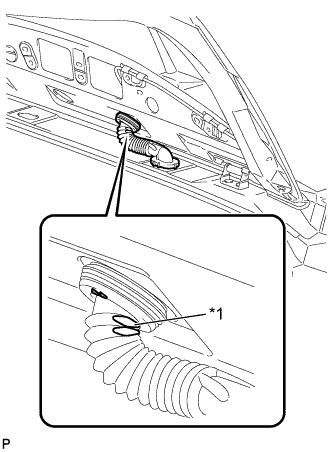
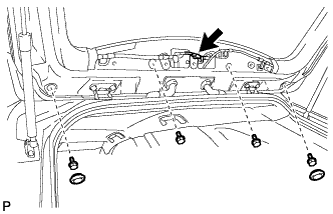
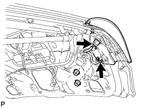
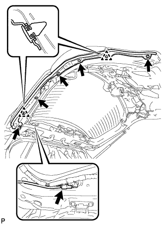
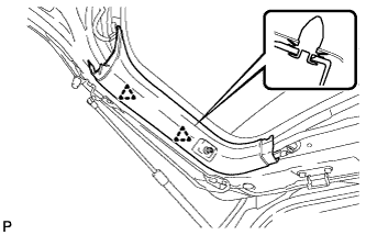
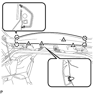
Pass the No. 3 antenna cord sub-assembly with washer hose through the vehicle body as shown in the illustration.
-
Engage the 2 claws.
-
Connect the grommet to the back door.
-
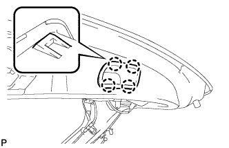
Engage the 4 clamps.
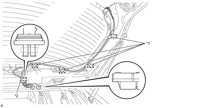
Text in Illustration *1 Clamp *2 Grommet -
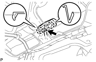
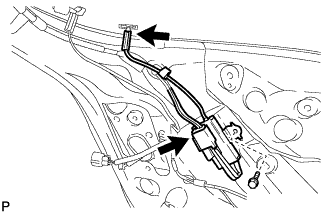
Connect the connector and engage the clamp.
-
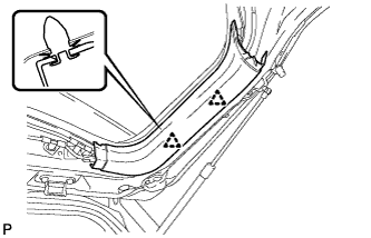
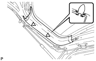
Engage the 7 clamps.
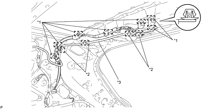
Text in Illustration *1 Clamp *2 Hook *3 Washer Hose - - -
Engage the 4 hooks to connect the washer hose.
-
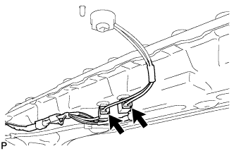
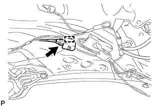
Connect the 2 connectors.
-
Text in Illustration *1 Flat Area Set the position of the grommet as shown in the illustration.
Tech Tips
Flat area to be oriented outside the vehicle.
-
-
INSTALL ROOF HEADLINING ASSEMBLY
Tech Tips
Refer to the procedure from Install Roof Headlining Assembly Click here.
-
INSTALL REAR WIPER MOTOR AND BRACKET ASSEMBLY
-
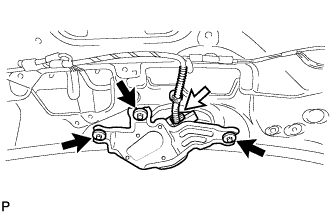
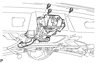
Install the rear wiper motor and bracket assembly with the 3 bolts.
- Torque:
- 5.5 N*m { 56 kgf*cm, 49 in.*lbf }
-
Connect the connector.
-
-
INSTALL REAR WIPER MOTOR GROMMET
-
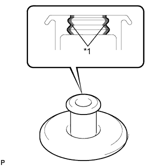
Text in Illustration *1 MP grease Apply MP grease to the entire surface of the wiper motor grommet lip.
Tech Tips
Make sure that the hole does not get clogged with grease and the grooves on the lip are filled with grease.
-
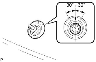
Install the rear wiper motor grommet with the position mark facing upward as shown in the illustration.
-
-
INSTALL REAR WIPER ARM AND BLADE ASSEMBLY
-
Stop the wiper motor at the automatic stop position.
-
When reusing the rear wiper arm and blade assembly:
-
Text in Illustration *1 Wiper Arm Serration Clean the wiper arm serrations.
-
-
When reusing the rear wiper motor and bracket assembly:
-
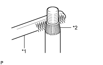
Text in Illustration *1 Wire Brush *2 Wiper Pivot Serration Clean the wiper pivot serrations with a wire brush.
-
-
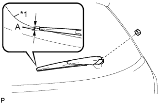
Text in Illustration *1 Ceramic Hard Line Install the rear wiper arm and blade assembly with the nut to the position shown in the illustration.
Standard Measurement Area Dimension A 7.5 mm (0.295 in.) - Torque:
- 5.5 N*m { 56 kgf*cm, 49 in.*lbf }
-
Operate the rear wiper while spraying washer fluid onto the back door glass. Make sure that the rear wiper functions properly and the wiper does not come into contact with the vehicle body.
-
-
INSTALL REAR WIPER ARM HEAD CAP
-
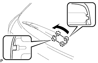
Engage the 4 claws to install the cap as shown in the illustration.
-
-
INSTALL REAR WASHER NOZZLE
-
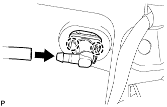
Engage the 2 claws to install the rear washer nozzle.
-
Connect the washer hose.
-
-
INSPECT REAR WASHER NOZZLE
-
With the engine running, check where the washer fluid hits the windshield.
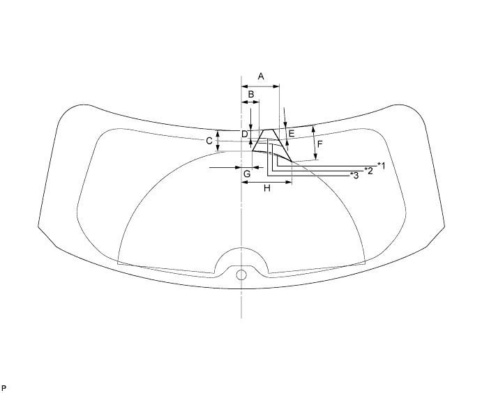
Standard Measurement Area Dimension Area Dimension A 134.4 mm (5.29 in.) B 63.5 mm (2.50 in.) C 75.4 mm (2.97 in.) D 28.2 mm (1.11 in.) E 38.1 mm (1.50 in.) F 120 mm (4.72 in.) G 38.7 mm (1.52 in.) H 180.1 mm (7.09 in.) Text in Illustration *1 Minimum Spray *2 Maximum Spray *3 Nominal Spray - - OK Washer fluid hits the windshield in the area shown in the illustration.
-
-
ADJUST REAR WASHER NOZZLE
-
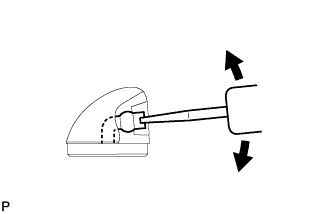
Using a screwdriver, adjust the direction of the rear washer nozzle.
Note
Do not use a safety pin or other pointed tools. Doing so may damage the inside of the washer nozzle.
Tech Tips
Use a thin-bladed screwdriver with an approximately 1 mm (0.0394 in.) thick tip.
-
-
INSTALL REAR SPOILER ASSEMBLY
-
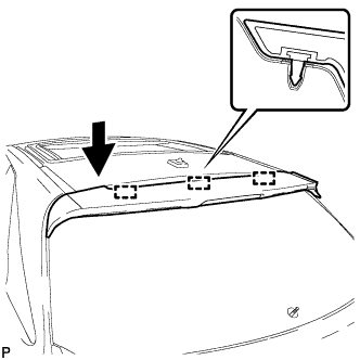
Engage the 3 pins to install the rear spoiler assembly.
-
Install the 4 bolts.
-
Install the 2 hole plugs.
-
Connect the connector.
-
-
INSTALL LICENSE PLATE LIGHT ASSEMBLY
-
Engage the 2 claws to install the license plate light assembly.
-
Connect the connector.
-
-
INSTALL BACK DOOR OUTSIDE GARNISH SUB-ASSEMBLY
-
Install the 5 stud bolts and 5 new gaskets to the back door outside garnish sub-assembly.
-
Install 16 new clips (back door moulding clip) to the back door outside garnish sub-assembly.
-
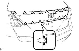
Engage the 16 clips to install the back door outside garnish sub-assembly.
-
Install the 5 nuts.
-
Connect each connector.
-
-
INSTALL REAR LIGHT ASSEMBLY LH
-
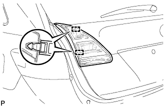
Engage the 2 pins to install the rear light assembly.
-
Install the 2 nuts.
- Torque:
- 6.8 N*m { 69 kgf*cm, 60 in.*lbf }
-
Connect the 2 connectors.
-
-
INSTALL REAR LIGHT ASSEMBLY RH
Tech Tips
Use the same procedure for the RH side and LH side.
-
INSTALL AMPLIFIER ANTENNA ASSEMBLY
-
Install the No. 2 amplifier antenna assembly with the bolt.
- Torque:
- 8.0 N*m { 82 kgf*cm, 71 in.*lbf }
-
Connect the 2 connectors.
-
-
INSTALL POWER BACK DOOR WARNING BUZZER (w/ Power Back Door)
-
Engage the clamp to install the power back door warning buzzer.
-
Connect the connector.
-
-
INSTALL BACK DOOR LOWER DAMPER STAY BRACKET LH
-
Clean the threaded portion on the vehicle body with a non-residue solvent.
-
Apply adhesive to the threads of the 2 bolts.
Adhesive Toyota Genuine Adhesive 1324, Three Bond 1324 or equivalent -
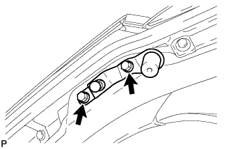
Install the back door lower damper stay bracket with the 2 bolts.
- Torque:
- 8.0 N*m { 82 kgf*cm, 71 in.*lbf }
-
-
INSTALL BACK DOOR LOWER DAMPER STAY BRACKET RH
Tech Tips
Use the same procedure for the RH side and LH side.
-
INSTALL BACK DOOR STAY ASSEMBLY LH
Note
-
Avoid touching the piston rod as much as possible to prevent foreign matter from attaching to it. Be sure to hold the cylinder while servicing.
-
Do not wear cotton gloves or other similar materials when handling the piston rod. Fibers may attach to the rod and result in gas leaks.
-
Do not apply any horizontal load to the door stay in order to prevent the rod from deforming.
-
When reusing the back door stay assembly:
-
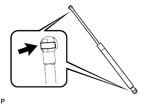
Install the 2 stop rings to the back door stay assembly.
-
-
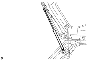
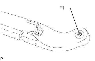
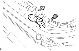
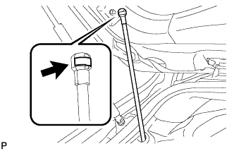
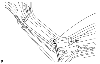
Install the back door stay assembly.
Note
Install the back door stay assembly while supporting the back door by hand.
-
Check that the back door stay assembly is engaged in the ball joint and that the back door stay assembly cannot be pulled out.
-
-
INSTALL BACK DOOR STAY ASSEMBLY RH
Tech Tips
Use the same procedure for the RH side and LH side.
-
INSTALL POWER BACK DOOR TOUCH SENSOR ASSEMBLY LH (w/ Power Back Door)
-
Tie the string to the wire near the connector of the power back door touch sensor assembly.
Tech Tips
Use the string that was left in the door during removal of the touch sensor assembly.
-
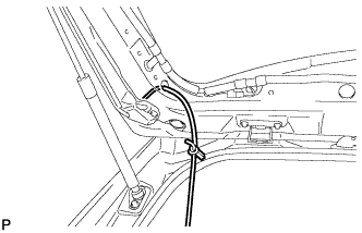
Pull the string to help pass the connector through the inside of the back door frame.
-
Engage the 2 clips.
-
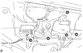
Install the power back door touch sensor assembly with the 5 bolts.
-
Connect the connector.
-
-
INSTALL POWER BACK DOOR TOUCH SENSOR ASSEMBLY RH (w/ Power Back Door)
Tech Tips
Use the same procedure for the RH side and LH side.
-
INSTALL BACK DOOR LOCK ASSEMBLY
-
Apply MP grease to the sliding parts of the back door lock assembly.
-
Apply adhesive to the threads of the bolt.
Adhesive Toyota Genuine Adhesive 1324, Three Bond 1324 or equivalent -
Install the back door lock assembly with the 3 bolts.
- Torque:
- 8.0 N*m { 82 kgf*cm, 71 in.*lbf }
-
Install the bolt.
- Torque:
- 8.0 N*m { 82 kgf*cm, 71 in.*lbf }
-
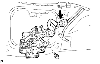
Engage the clamp.
-
Connect the connector.
-
-
INSTALL POWER BACK DOOR CLOSER SWITCH ASSEMBLY (w/ Power Back Door)
-
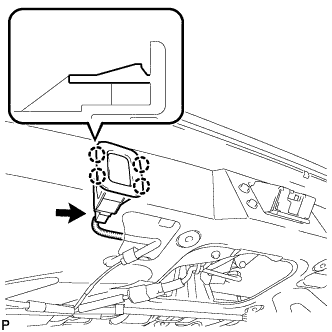
Engage the 4 claws to install the power back door closer switch assembly.
-
Connect the connector.
-
-
INSTALL DOOR PULL HANDLE
-
Engage the 4 claws to install the back door pull handle.
-
-
INSTALL BACK DOOR TRIM COVER RH
-
Engage the 2 clips to install the back door trim cover RH.
-
-
INSTALL UPPER BACK DOOR STAY BRACKET LH
-
Install the upper back door stay bracket LH with the 2 bolts.
- Torque:
- 13 N*m { 133 kgf*cm, 10 ft.*lbf }
-
-
INSTALL BACK DOOR TRIM COVER LH (w/o Power Back Door)
-
Engage the 2 clips to install the back door trim cover LH.
-
-
INSTALL BACK DOOR TRIM COVER LH (w/ Power Back Door)
-
Engage the 2 clips to install the back door trim cover LH.
-
-
CONNECT POWER BACK DOOR ROD (w/ Power Back Door)
-
Install the stop ring to the power back door rod.
-
Install the power back door rod.
-
-
INSTALL BACK DOOR PANEL TRIM ASSEMBLY
-
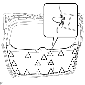
Engage the 16 clips and install the back door panel trim assembly.
-
-
INSTALL UPPER BACK WINDOW PANEL TRIM
-
Engage the 4 clips and 4 claws to install the upper back window panel trim.
-