BACK DOOR DISASSEMBLY

-
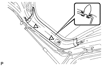
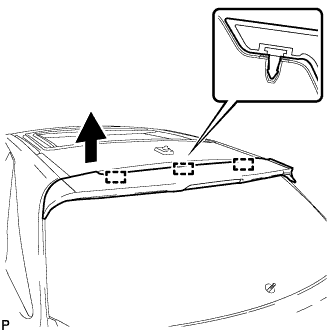
REMOVE UPPER BACK WINDOW PANEL TRIM
-
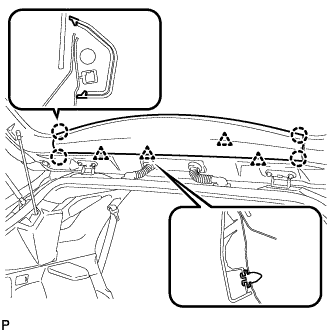
Disengage the 4 clips and 4 claws, and remove the upper back window panel trim.
-
-
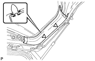
REMOVE BACK DOOR PANEL TRIM ASSEMBLY
-
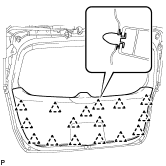
Disengage the 16 clips and remove the back door panel trim assembly.
-
-
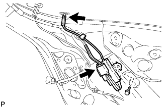
DISCONNECT POWER BACK DOOR ROD (w/ Power Back Door)
-
Text in Illustration *1 Protective Tape Using a screwdriver, remove the stop ring along the groove.
Tech Tips
Tape the screwdriver tip before use.
-
Release the ball joint and disengage the power back door rod.
-
-
REMOVE BACK DOOR TRIM COVER LH (w/o Power Back Door)
-
Disengage the 2 clips and remove the back door trim cover LH.
-
-
REMOVE BACK DOOR TRIM COVER LH (w/ Power Back Door)
-
Disengage the 2 clips and remove the back door trim cover LH.
-
-
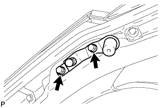
REMOVE UPPER BACK DOOR STAY BRACKET LH (w/ Power Back Door)
-
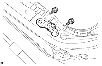
Remove the 2 bolts and upper back door stay bracket LH.
-
-
REMOVE BACK DOOR TRIM COVER RH
-
Disengage the 2 clips and remove the back door trim cover RH.
-
-
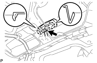
REMOVE DOOR PULL HANDLE
-
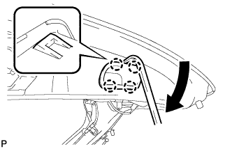
Using a moulding remover, disengage the 4 claws and remove the back door pull handle as shown in the illustration.
-
-
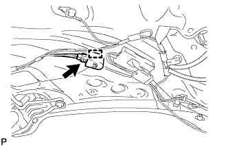
REMOVE POWER BACK DOOR CLOSER SWITCH ASSEMBLY (w/ Power Back Door)
-
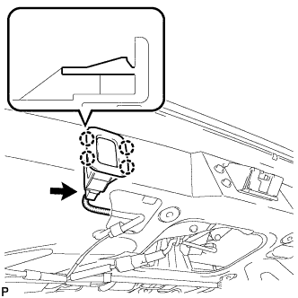
Disconnect the connector.
-
Disengage the 4 claws and remove the power back door closer switch assembly.
-
-
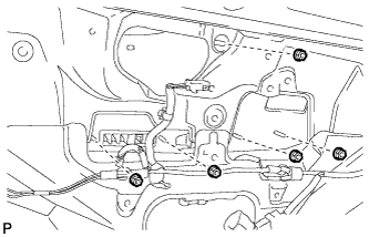
REMOVE BACK DOOR LOCK ASSEMBLY
-
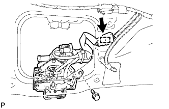
Disconnect the connector.
-
Disengage the clamp.
-
Remove the bolt.
-
Remove the 3 bolts and back door lock assembly.
-
-
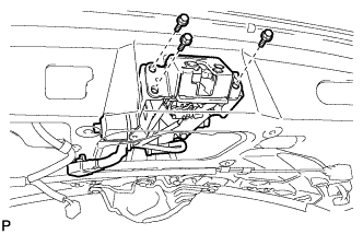
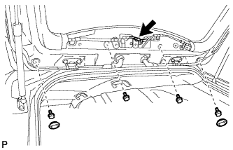
REMOVE POWER BACK DOOR TOUCH SENSOR ASSEMBLY LH (w/ Power Back Door)
-
Disconnect the connector.
-
Remove the 5 bolts.
-
Disengage the 2 clips.
-
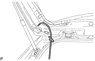
Tie a string to the wire near the connector of the power back door touch sensor assembly.
-
Remove the power back door touch sensor assembly.
Tech Tips
Leave the string inside the back door frame because it will be used for installation.
-
Untie the string from the power back door touch sensor assembly.
-
-
REMOVE POWER BACK DOOR TOUCH SENSOR ASSEMBLY RH (w/ Power Back Door)
Tech Tips
Use the same procedure for the RH side and LH side.
-
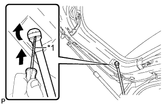
REMOVE BACK DOOR STAY ASSEMBLY LH
Note
-
Avoid touching the piston rod as much as possible to prevent foreign matter from attaching to it. Be sure to hold the cylinder while servicing.
-
Do not wear cotton gloves or other similar materials when handling the piston rod. Fibers may attach to the rod and result in gas leaks.
-
Do not apply any horizontal load to the door stay in order to prevent the piston rod from deforming.
-
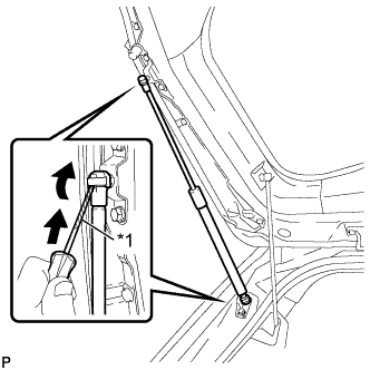
Text in Illustration *1 Protective Tape Using a screwdriver, remove the stop ring along the groove.
Tech Tips
Tape the screwdriver tip before use.
-
Release the ball joint and remove the back door stay assembly.
Note
Remove the back door stay assembly while supporting the back door by hand.
-
-
REMOVE BACK DOOR STAY ASSEMBLY RH
Tech Tips
Use the same procedure for the RH side and LH side.
-
REMOVE BACK DOOR LOWER DAMPER STAY BRACKET LH
-
Remove the 2 bolts and back door lower damper stay bracket.
-
-
REMOVE BACK DOOR LOWER DAMPER STAY BRACKET RH
Tech Tips
Use the same procedure for the RH side and LH side.
-
REMOVE POWER BACK DOOR WARNING BUZZER (w/ Power Back Door)
-
Disconnect the connector.
-
Disengage the clamp to remove the power back door warning buzzer.
-
-
REMOVE AMPLIFIER ANTENNA ASSEMBLY
-
Disconnect the 2 connectors.
-
Remove the bolt and No. 2 amplifier antenna assembly.
-
-
REMOVE REAR LIGHT ASSEMBLY LH
-
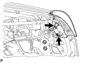
Disconnect the 2 connectors.
-
Remove the 2 nuts.
-
Disengage the 2 pins and remove the rear light assembly.
-
-
REMOVE REAR LIGHT ASSEMBLY RH
Tech Tips
Use the same procedure for the RH side and LH side.
-
REMOVE BACK DOOR OUTSIDE GARNISH SUB-ASSEMBLY
-
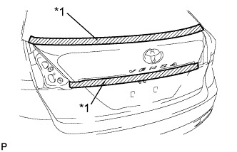
Text in Illustration *1 Protective Tape Put protective tape around the back door outside garnish sub-assembly.
-
Disconnect each connector.
-
Remove the 5 nuts.
-
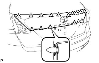
Disengage the 16 clips and remove the back door outside garnish sub-assembly.
-
Remove the 16 clips (back door moulding clip) from the back door outside garnish sub-assembly.
-
Remove the 5 gaskets and 5 stud bolts from the back door outside garnish sub-assembly.
-
-
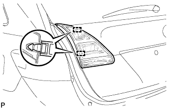
REMOVE LICENSE PLATE LIGHT ASSEMBLY
-
Disconnect the connector.
-
Disengage the 2 claws and remove the license plate light assembly.
-
-
REMOVE REAR SPOILER ASSEMBLY
-
Disconnect the connector.
-
Remove the 2 hole plugs.
-
Remove the 4 bolts.
-
Disengage the 3 pins to remove the rear spoiler assembly.
-
-
REMOVE REAR WASHER NOZZLE
-
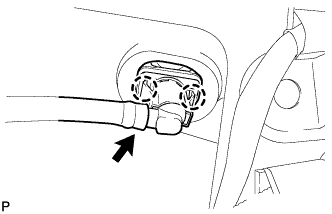
Disconnect the washer hose.
-
Disengage the 2 claws and remove the rear washer nozzle.
-
-
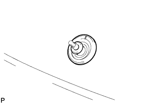
REMOVE REAR WIPER ARM HEAD CAP
-
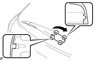
Disengage the 4 claws and remove the rear wiper arm head cap as shown in the illustration.
-
-
REMOVE REAR WIPER ARM AND BLADE ASSEMBLY
-
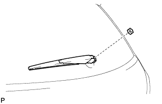
Remove the nut and the rear wiper arm and blade assembly.
-
-
REMOVE REAR WIPER MOTOR GROMMET
-
Remove the rear wiper motor grommet.
-
-
REMOVE REAR WIPER MOTOR AND BRACKET ASSEMBLY
-
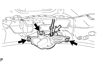
Disconnect the connector.
-
Remove the 3 bolts and the rear wiper motor and bracket assembly.
-
-
REMOVE ROOF HEADLINING ASSEMBLY
Tech Tips
Refer to the procedure up to Remove Roof Headlining Assembly Click here.
-
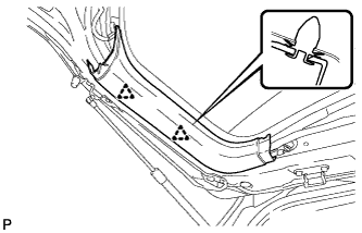
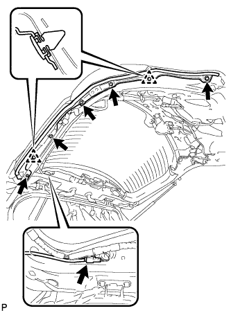
REMOVE NO. 3 ANTENNA CORD SUB-ASSEMBLY
-
Disconnect the 2 connectors.
-
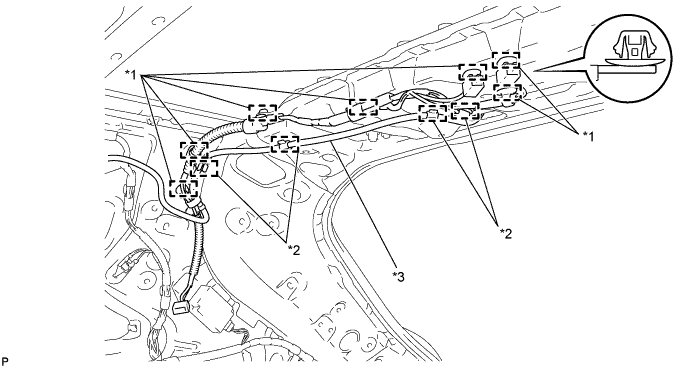
Disengage the 4 hooks and disconnect the washer hose.
-
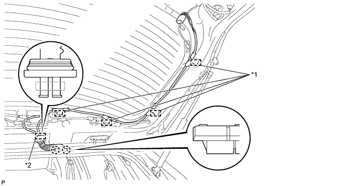
Disengage the 7 clamps.
Text in Illustration *1 Clamp *2 Hook *3 Washer Hose - - -
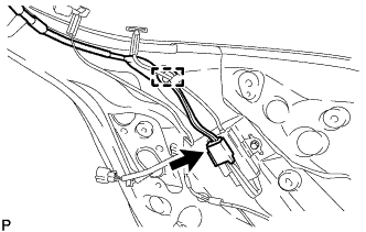
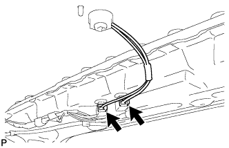
Disconnect the connector and disengage the clamp.
-
Disengage the 4 clamps.
Text in Illustration *1 Clamp *2 Grommet -
Disconnect the grommet from the back door.
-
Disengage the 2 claws.
-
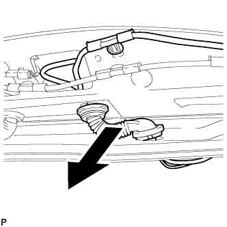
Remove the No. 3 antenna cord sub-assembly with the washer hose as shown in the illustration.
-