FRONT DOOR REASSEMBLY

-
PRECAUTION
Note
After turning the ignition switch off, waiting time may be required before disconnecting the cable from the negative (-) battery terminal. Therefore, make sure to read the disconnecting the cable from the negative (-) battery terminal notices before proceeding with work Click here.
-
REPAIR INSTRUCTION
-
Clean the vehicle body surface.
-
Using a heat light, heat the vehicle body surface.
Heating Temperature Item Temperature Vehicle Body 40 to 60°C (104 to 140°F) Note
Do not heat the vehicle body excessively.
-
Wipe off any tape adhesive residue with cleaner.
-
-
Installation temperature
-
When the ambient temperature is below 15°C (59°F), perform the installation procedure after warming the vehicle body surface (installation surface of the door frame) and tape up to between 20 and 30°C (68 and 86°F) using a heat light. When the ambient temperature is above 35°C (95°F), cool the vehicle body surface (installation surface of the door frame) and tape down to between 20 and 30°C (68 and 86°F) prior to installation.
Tech Tips
-
The most appropriate temperature for installing the tape is 25°C (77°F).
-
When the temperature is low, the tape turns stiff and comes off easily. When the temperature is high, the tape looses elasticity.
-
-
-
Before installation
-
Remove any coating roughness or dirt on and around the vehicle body surface where the tape will be installed (installation surface of the door frame). If any roughness or dirt remains when pressing the tape onto the surface, air will be trapped under the tape and result in a poor appearance.
Tech Tips
Spray water on the shop floor to settle any dust.
-
-
Key points for handling the tape
-
The tape bends and rolls up easily. Store the tape between flat pieces of cardboard or other similar objects and keep it dry and level.
Note
Do not bend the tape or leave it in high temperature places.
-
-
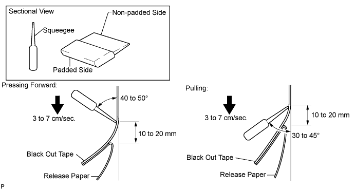
Key points for installation of the tape (how to use a squeegee and installation procedure for flat surfaces)
Note
-
Position the tape accurately to achieve a neat finish and to avoid peeling.
-
The tape cannot be reused because it deforms and will not fit any more after being removed.
-
To avoid air bubbles, slightly raise the part of the tape that is going to be applied so that its adhesive surface does not touch the vehicle body while applying the tape. Tilt the squeegee at 40 to 50° (pressing forward) or 30 to 45° (pulling) to the vehicle body surface and press the tape onto the vehicle body surface with a force of 20 to 30 N (2 to 3 kgf) at a constant slow speed of 3 to 7 cm (1.18 to 2.76 in.) per second.
Note
Be sure to observe the specified pressing speed, force, and angle of the squeegee to avoid wrinkles or air bubbles.
Tech Tips
-
Either angle of the squeegee (pressing forward or pulling) is acceptable.
-
Be sure to apply the tape while removing the release paper 10 to 20 mm (0.394 to 0.787 in.) from the edge of the squeegee.
-
-
-
Key points for installation of the tape (how to use a squeegee and installation procedure for hemmed surfaces)
-
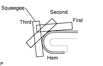
If it is difficult to apply the tape, install it in several steps as shown in the illustration. Use your fingers or the padded surface of a squeegee to slowly apply the tape to the hem of the vehicle, especially for a small hem.
Tech Tips
When applying tape to the backside of a hem, remove the release paper and use your fingers or the padded surface of a squeegee.
-
-
Key points for installation of the tape (how to use a squeegee and installation procedure for corners)
-
Remove the release paper and apply the tape carefully with your fingers.
-
Before applying the tape to each corner, heat the tape using a heat light and gradually apply it, avoiding wrinkles on the tape to achieve a neat finish.
-
-
Check after installation
-
After completing the application, check if the tape is applied neatly. If the tape is not applied neatly, reapply using new tape.
Note
Do not reuse the tape.
-
-
-
INSTALL FRONT DOOR FRONT WINDOW FRAME MOULDING
-
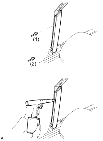
Engage the front door front window frame moulding to the door frame.
-
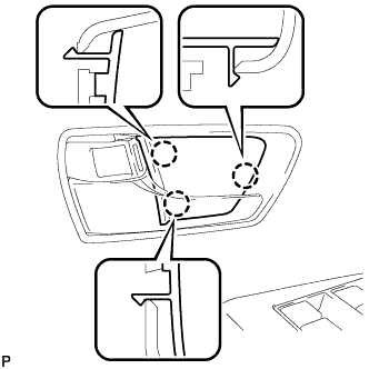
Using an air riveter or hand riveter with a nose piece, install the front door front window frame moulding with 2 new rivets.
Tech Tips
-
Tighten the 2 rivets in the order shown in the illustration.
-
If the rivet cannot be cut, pull it once and cut it.
Note
-
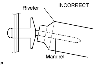
Do not pry the rivet with the riveter, as this will cause damage to the riveter and mandrel.
-
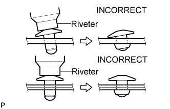
Confirm that the rivets are seated properly against the moulding. Do not tilt the riveter when installing the rivet to the moulding. Do not leave any space between the rivet head and moulding.
-
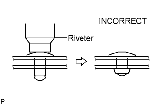
Do not leave any space between the moulding and door frame. Firmly hold the 2 items together while installing the rivet.
-
-
-
INSTALL FRONT DOOR UPPER WINDOW FRAME MOULDING
-
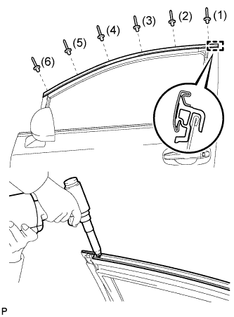
Engage the guide and front door upper window frame moulding to the door frame.
-
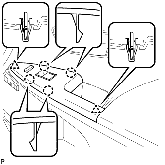
Using an air riveter or hand riveter with a nose piece, install the front door upper window frame moulding with 6 new rivets.
Tech Tips
-
Tighten the 6 rivets in the order shown in the illustration.
-
If the rivet cannot be cut, pull it once and cut it.
Note
-
Do not pry the rivet with the riveter, as this will cause damage to the riveter and mandrel.
-
Confirm that the rivets are seated properly against the moulding. Do not tilt the riveter when installing the rivet to the moulding. Do not leave any space between the rivet head and moulding.
-
Do not leave any space between the moulding and door frame. Firmly hold the 2 items together while installing the rivet.
-
-
-
INSTALL FRONT DOOR PANEL SUB-ASSEMBLY
-
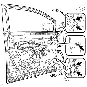
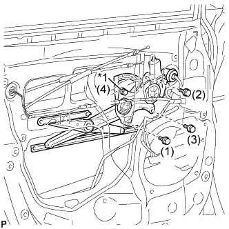
Install the front door panel sub-assembly with the 4 bolts <B>.
- Torque:
- 26 N*m { 265 kgf*cm, 19 ft.*lbf }
Note
To prevent damage, when installing the front door panel sub-assembly, make sure that there are enough people available to hold it securely.
-
Apply adhesive to the threads of the bolt <A>.
Adhesive Toyota Genuine Adhesive 1324, Three Bond 1324 or equivalent -
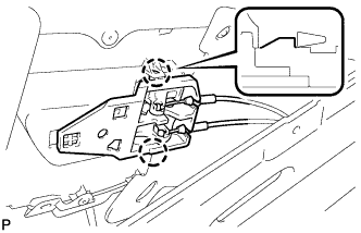
Engage the front door check assembly with the bolt <A>.
- Torque:
- 29 N*m { 296 kgf*cm, 21 ft.*lbf }
-
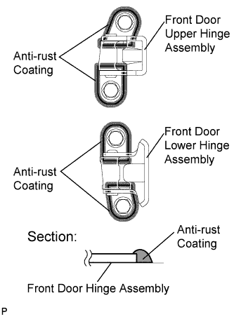
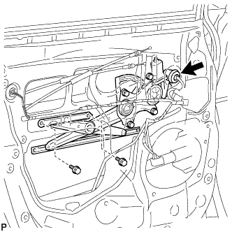
Using a brush, apply anti-rust coating to the front door hinge assembly as shown in the illustration.
-
Connect each connector.
-
-
INSTALL COWL SIDE TRIM SUB-ASSEMBLY
-
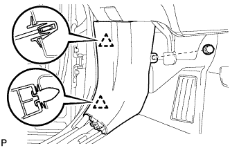
Engage the 2 clips to install the cowl side trim sub-assembly LH.
-
Install the clip.
-
-
INSTALL FRONT DOOR SCUFF PLATE
-
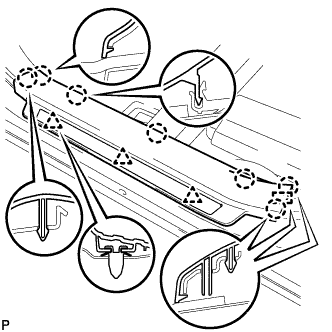
Engage the guide, 3 clips and the 7 claws to install the front door scuff plate LH.
-
-
INSTALL FRONT DOOR REAR WINDOW FRAME MOULDING
Tech Tips
When installing the front door rear window frame moulding, heat the vehicle body and front door rear window frame moulding using a heat light.
Heating Temperature Item Temperature Vehicle Body 40 to 60°C (104 to 140°F) Moulding 20 to 30°C (68 to 86°F) Note
Do not heat the vehicle body or front door rear window frame moulding excessively.
-
Clean the vehicle body surface.
-
Using a heat light, heat the vehicle body surface.
-
Remove the double-sided tape from the vehicle body.
-
Wipe off any tape adhesive residue with cleaner.
-
-
Clean the front door rear window frame moulding (if reusing the front door rear window frame moulding).
-
Using a heat light, heat the front door rear window frame moulding.
-
Remove the double-sided tape from the front door rear window frame moulding.
-
Wipe off any tape adhesive residue with cleaner.
-
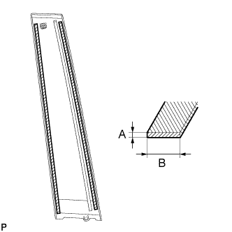
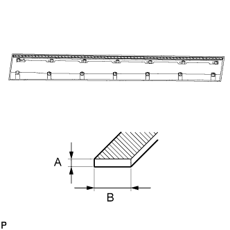
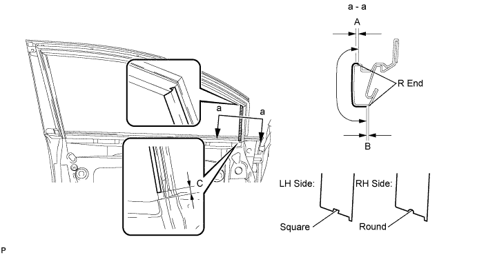
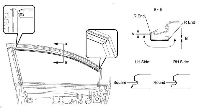
Apply new double-sided tape to the front door rear window frame moulding.
Item Dimension A 0.8 mm (0.0315 in.) B 5.0 mm (0.197 in.)
-
-
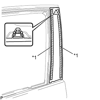
Text in Illustration *1 Double-sided Tape Install the front door rear window frame moulding.
-
Using a heat light, heat the vehicle body and front door rear window frame moulding.
-
Remove the peeling paper from the face of the front door rear window frame moulding.
Tech Tips
After removing the peeling paper, keep the exposed adhesive free from foreign matter.
-
Install the front door rear window frame moulding with the clip.
-
-
-
INSTALL FRONT DOOR BELT MOULDING
-
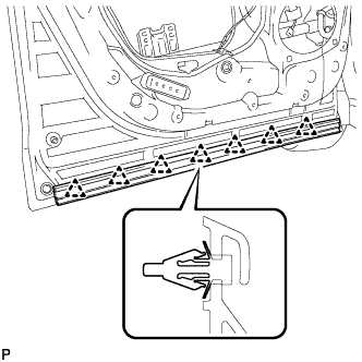
Engage the 5 claws to install the front door belt moulding.
-
Install the clip.
-
-
INSTALL FRONT DOOR OUTSIDE MOULDING
-
Clean the vehicle body surface.
-
Using a heat light, heat the vehicle body surface.
-
Remove the double-sided tape from the vehicle body.
-
Wipe off any tape adhesive residue with cleaner.
-
-
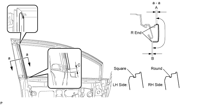
Clean the front door outside moulding.
Dimension Measurement A 1.2 mm (0.0472 in.) B 6.0 mm (0.236 in.)
-
Using a heat light, heat the front door outside moulding.
-
Remove the double-sided tape from the front door outside moulding.
-
Wipe off any tape adhesive residue with cleaner.
-
Apply new double-sided tape to the front door outside moulding.
-
-
Install 13 new clips (No. 1 outside moulding clip) to the front door outside moulding.
-
Install the outside moulding retainer to the front door outside moulding.
-
Install the front door outside moulding.
-
Using a heat light, heat the vehicle body and front door outside moulding.
-
Remove the release paper from the front door outside moulding.
Tech Tips
After removing the release paper, keep the exposed adhesive free from foreign matter.
-
Engage the 13 clips and install the front door outside moulding.
-
-
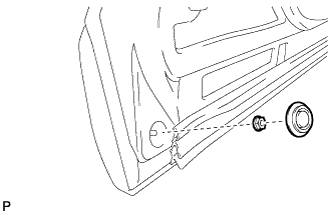
Install the nut and hole plug.
-
-
INSTALL NO. 1 BLACK OUT TAPE
-
Refer to the illustration to position the No. 1 black out tape.
Standard Measurement Dimension Measurement A +1.5 mm (+0.0591 in.) B -1.0 mm (-0.0394 in.) C 7.0 mm (0.276 in.) -
Remove the release paper and apply the tape.
-
-
INSTALL FRONT DOOR LOWER OUTSIDE STRIPE
-
Refer to the illustration to position the front door lower outside stripe.
Standard Measurement Dimension Measurement A +1.5 mm (+0.0591 in.) B -1.0 mm (-0.0394 in.) C 7.5 mm (0.295 in.) -
Remove the release paper and apply the stripe.
-
-
INSTALL FRONT DOOR STRIPE
-
Refer to the illustration to position the front door stripe.
Standard Measurement Dimension Measurement A +1.5 mm (+0.0591 in.) B -1.0 mm (-0.0394 in.) -
Remove the release paper and apply the stripe.
-
-
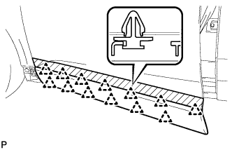
INSTALL FRONT DOOR PANEL PROTECTOR
-
Engage the 7 clips and install the front door panel protector.
-
-
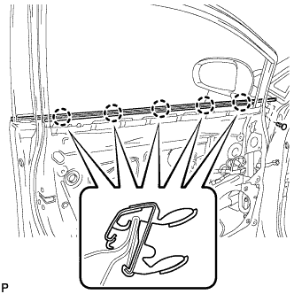
INSTALL FRONT DOOR WEATHERSTRIP
-
If reusing the front door weatherstrip.
-
Clean the front door weatherstrip.
-
Remove the double-sided tape from the front door weatherstrip.
-
Wipe off any tape adhesive residue with cleaner.
-
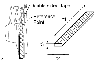
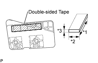
Area Dimension *1 75.0 mm (2.952 in.) *2 8.0 mm (0.315 in.) *3 0.8 mm (0.0315 in.) Apply new double-sided tape to the front door weatherstrip as shown in the illustration.
-
-
Clean the front door panel sub-assembly.
-
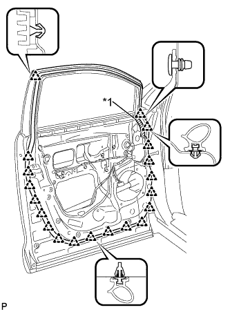
Text in Illustration *1 Double-sided Tape Engage the 20 clips and install the front door weatherstrip.
-
-
INSTALL FRONT DOOR CHECK ASSEMBLY
-
Apply MP grease to the sliding areas of the front door check assembly.
-
Apply adhesive to the threads of the bolt.
Adhesive Toyota Genuine Adhesive 1324, Three Bond 1324 or equivalent -
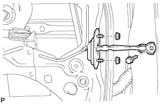
Install the front door check assembly with the bolt and 2 nuts.
- Torque:
- Bolt
- 29 N*m { 296 kgf*cm, 21 ft.*lbf }
- Nut
- 5.5 N*m { 56 kgf*cm, 49 in.*lbf }
-
-
INSTALL FRONT DOOR LOCK OPEN ROD
-
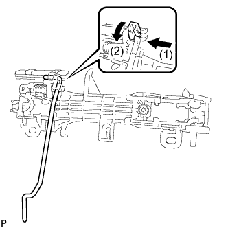
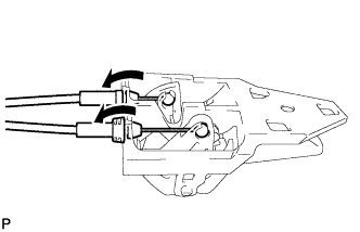
Install the front door lock open rod as indicated by the arrows, in the order shown in the illustration.
-
-
INSTALL FRONT DOOR OUTSIDE HANDLE FRAME SUB-ASSEMBLY
-
Apply MP grease to the sliding parts on the front door outside handle frame sub-assembly.
-
Engage the door handle nut and claw.
-
Using a T30 "TORX" socket wrench, install the front door outside handle frame sub-assembly with the screw.
- Torque:
- 4.0 N*m { 41 kgf*cm, 35 in.*lbf }
-
-
INSTALL ELECTRICAL KEY WIRE HARNESS (w/ Smart Entry and Start System)
-
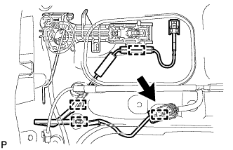
Engage the 4 clamps and install the electrical key wire harness.
-
Connect the connector.
-
-
INSTALL FRONT DOOR INSIDE LOCKING CABLE ASSEMBLY
-
Install the front door inside locking cable assembly.
-
Engage the 3 claws.
-
-
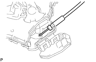
INSTALL FRONT DOOR LOCK REMOTE CONTROL CABLE ASSEMBLY
-
Install the front door lock remote control cable assembly.
-
-
INSTALL FRONT DOOR LOCK ASSEMBLY
Note
-
When reusing the removed front door lock assembly, replace the door lock wiring harness seal on the connector with a new one.
-
Do not allow grease or dust to adhere to the door lock wiring harness seal surface of the connector.
-
Reusing the door lock wiring harness seal or using a damaged door lock wiring harness seal may cause water intrusion. This may result in a malfunction of the front door lock assembly.
-
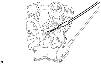
Apply MP grease to the sliding parts of the front door lock assembly.
-
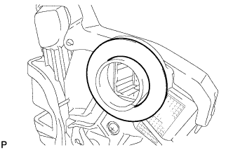
Install a new door lock wiring harness seal to the front door lock assembly.
-
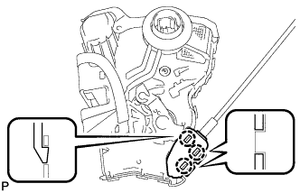
Insert the front door lock open rod to the front door lock assembly.
-
Make sure that the front door lock open rod is securely connected to the front door lock assembly.
-
Apply adhesive to the threads of the bolt.
Adhesive Toyota Genuine Adhesive 1324, Three Bond 1324 or equivalent -
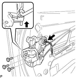
Using a T30 "TORX" socket wrench, install the front door lock assembly with the 3 screws.
- Torque:
- 5.0 N*m { 51 kgf*cm, 44 in.*lbf }
-
-
INSTALL FRONT DOOR REAR OUTSIDE HANDLE PAD
-
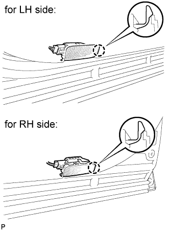
Engage the 2 claws and install the front door rear outside handle pad.
-
-
INSTALL FRONT DOOR FRONT OUTSIDE HANDLE PAD
-
Engage the 3 claws and install the front door front outside handle pad.
-
-
INSTALL FRONT DOOR OUTSIDE HANDLE ASSEMBLY (w/o Smart Entry and Start System)
-
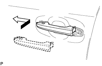
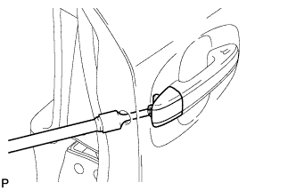
Insert the front end of the front door outside handle assembly into the front door outside handle frame.
-
Insert the rear end of the front door outside handle assembly into the front door outside handle frame, then slide the front door outside handle assembly toward the front of the vehicle to install it.
-
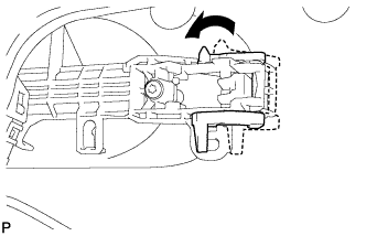
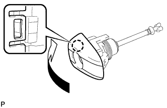
Move the lever back in the direction indicated by the arrow in the illustration to lock the door outside handle assembly.
-
-
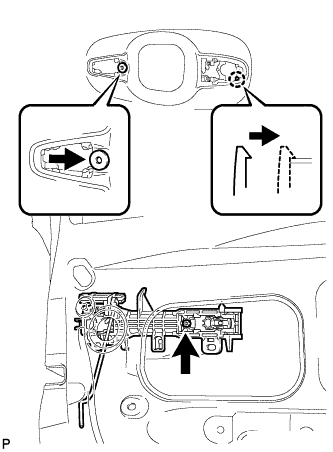
INSTALL FRONT DOOR OUTSIDE HANDLE ASSEMBLY (w/ Smart Entry and Start System)
-
Insert the front end of the front door outside handle assembly into the front door outside handle frame.
-
Insert the rear end of the front door outside handle assembly into the front door outside handle frame, then slide the front door outside handle assembly toward the front of the vehicle to install it.
-
Move the lever back in the direction indicated by the arrow in the illustration to lock the door outside handle assembly.
-
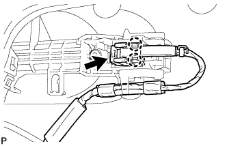
Connect the connector.
-
Engage the 2 claws.
-
-
INSTALL FRONT DOOR OUTSIDE HANDLE COVER (for Driver Side)
-
Engage the claw and install the front door outside handle cover to the front door lock cylinder.
-
-
INSTALL FRONT DOOR OUTSIDE HANDLE COVER (for Front Passenger Side)
-
Using a T30 "TORX" socket wrench, install the front door outside handle cover with the screw.
- Torque:
- 4.0 N*m { 41 kgf*cm, 35 in.*lbf }
-
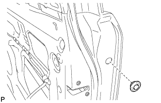
Install the hole plug.
-
-
INSTALL FRONT DOOR OUTSIDE HANDLE COVER WITH LOCK CYLINDER ASSEMBLY (for Driver Side)
-
Install the front door outside handle cover with lock cylinder assembly.
Tech Tips
Make sure that the front door lock cylinder rod is inserted into the front door lock assembly.
-
Using a T30 "TORX" socket wrench, install the front door lock cylinder with the screw.
- Torque:
- 4.0 N*m { 41 kgf*cm, 35 in.*lbf }
-
Install the hole plug.
-
-
INSTALL FRONT DOOR REAR LOWER FRAME SUB-ASSEMBLY
-
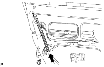
Install the front door rear lower frame sub-assembly with the bolt as shown in the illustration.
- Torque:
- 6.2 N*m { 63 kgf*cm, 55 in.*lbf }
-
-
INSTALL FRONT DOOR GLASS RUN
-
Install the front door glass run.
-
-
INSTALL FRONT DOOR NO. 2 STIFFENER CUSHION
-
If reusing the front door No. 2 stiffener cushion.
-
Clean the front door No. 2 stiffener cushion.
-
Remove the double-sided tape from the front door No. 2 stiffener cushion.
-
Wipe off any tape adhesive residue with cleaner.
-
Area Dimension *1 120.0 mm (4.724 in.) *2 20.0 mm (0.787 in.) *3 3.0 mm (0.118 in.) Apply new double-sided tape to the front door No. 2 stiffener cushion as shown in the illustration.
-
-
Clean the front door panel sub-assembly.
-
Text in Illustration *1 Double-sided Tape Insert the 2 claws and install the front door No. 2 stiffener cushion.
-
-
INSTALL FRONT POWER WINDOW REGULATOR MOTOR ASSEMBLY
Note
The regulator arm must be below the intermediate position when installing the power window regulator motor.
-
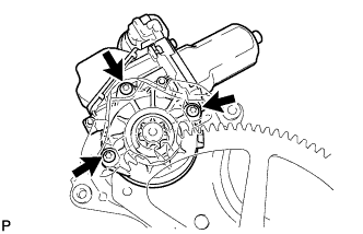
Using a T25 "TORX" socket wrench, install the front power window regulator motor assembly with the 3 screws.
- Torque:
- 5.4 N*m { 55 kgf*cm, 48 in.*lbf }
Tech Tips
A new front window regulator uses self-tapping screws to thread new installation holes when the self-tapping screws are inserted.
-
-
INSTALL FRONT DOOR WINDOW REGULATOR ASSEMBLY
-
Apply MP grease to the sliding parts of the front door window regulator assembly.
-
Install the temporary bolt to the front door window regulator assembly.
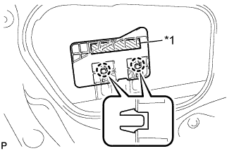
-
Text in Illustration *1 Temporary Bolt Temporarily install the front door window regulator assembly.
-
Tighten the temporary bolt and 3 bolts.
Tech Tips
Tighten the bolts and the nuts in the order shown in the illustration.
- Torque:
- 8.0 N*m { 82 kgf*cm, 71 in.*lbf }
-
Install the front door window regulator assembly with the 2 bolts.
- Torque:
- 8.0 N*m { 82 kgf*cm, 71 in.*lbf }
-
Connect the connector.
-
-
INSTALL FRONT DOOR GLASS SUB-ASSEMBLY
-
Connect the cable to the negative (-) battery terminal.
-
Connect the power window regulator master switch assembly and move the front door glass sub-assembly so that the door glass bolts can be seen.
-
Disconnect the cable from the negative (-) battery terminal and power window regulator master switch assembly.
-
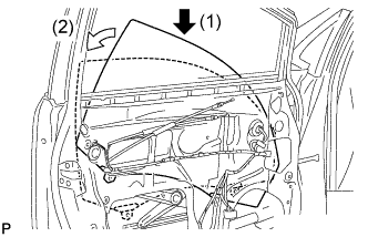
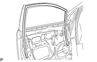
Insert the front door glass sub-assembly into the front door panel along the front door glass run as indicated by the arrows, in the order shown in the illustration.
-
Install the front door glass sub-assembly with the 2 bolts.
- Torque:
- 8.0 N*m { 82 kgf*cm, 71 in.*lbf }
-
-
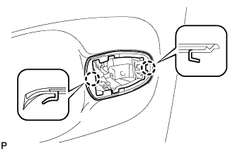
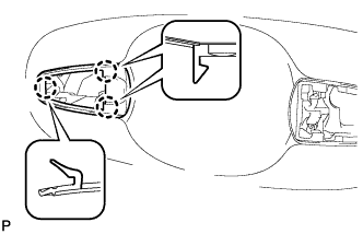
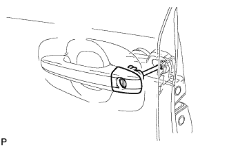
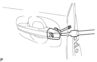
INSTALL OUTER REAR VIEW MIRROR ASSEMBLY
-
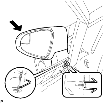
Engage the 3 claws to install the outer rear view mirror assembly as shown in the illustration.
-
Install the 3 nuts.
- Torque:
- 8.0 N*m { 82 kgf*cm, 71 in.*lbf }
-
Connect the connector.
-
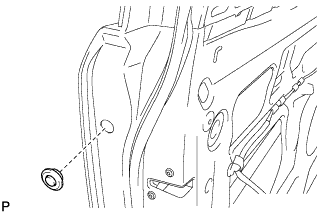
Install the hole plug.
-
-
INSTALL FRONT DOOR SERVICE HOLE COVER
-
Apply butyl tape to the front door panel.
-
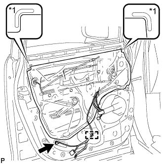
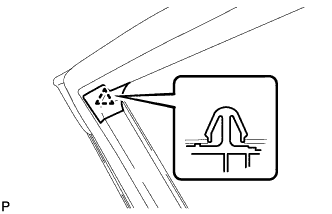
Text in Illustration *1 Reference Point Pass the front door lock remote control cable assembly and front door inside locking cable assembly through a new front door service hole cover.
-
Attach the front door service hole cover according to the reference points on the front door panel.
Note
Securely install the front door service hole cover preventing wrinkles and air bubbles.
-
Engage the clamp.
-
Install the bolt.
- Torque:
- 8.0 N*m { 82 kgf*cm, 71 in.*lbf }
-
-
INSTALL OUTER MIRROR CONTROL ECU ASSEMBLY (w/ Memory)
-
Install the outer mirror control ECU assembly with the 2 screws.
-
Connect the 2 connectors.
-
-
INSTALL FRONT NO. 1 SPEAKER ASSEMBLY
-
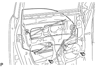
Install the front No. 1 speaker assembly with the 4 bolts.
-
Connect the connector.
-
-
INSTALL DOOR SIDE AIRBAG SENSOR
-
Check that the ignition switch is off.
-
Check that the cable is disconnected from the negative (-) battery terminal.
CAUTION:
Wait at least 90 seconds after disconnecting the cable from the negative (-) battery terminal to disable the SRS system.
-
Insert the pin (stopper) into the door hole and install the door side airbag sensor to the vehicle with the bolt.
- Torque:
- 9.0 N*m { 92 kgf*cm, 80 in.*lbf }
Note
-
If the door side airbag sensor has been dropped, or there are any cracks, dents or other defects in the case or connector, replace it with a new one.
-
When installing the door side airbag sensor, be careful that the SRS wiring does not interfere with or is not pinched between other parts.
-
Make sure that the pin (stopper) is securely inserted into the door hole.
-
Tighten the bolt while holding the door side airbag sensor because the door side airbag sensor pin (stopper) is easily damaged.
-
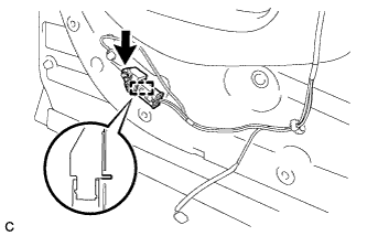
Connect the connector to the door side airbag sensor.
Note
When connecting the airbag connector, take care not to damage the airbag wire harness.
-
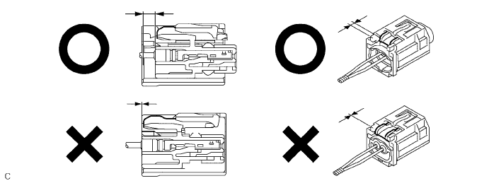
Before connecting the connector, check that the position of the white housing lock is correct as shown in the illustration.
-
Be sure to engage the connectors until they are locked (When locking, make sure that a click sound can be heard).
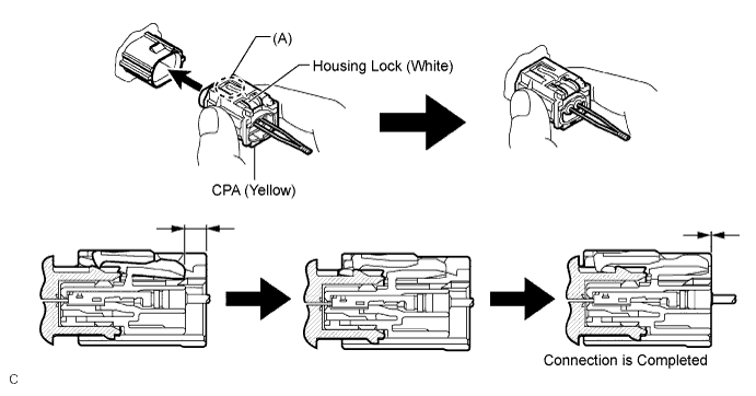
Tech Tips
When engaged, the white housing lock will slide. Be sure not to hold the white housing lock and part (A), as it may result in an insecure fit.
-
-
Check that there is no looseness in the installation parts of the door side airbag sensor.
-
-
INSTALL DOOR FRAME GARNISH
-
Engage the clip to install a new door frame garnish.
-
-
INSTALL SEAT MEMORY SWITCH (w/ Memory)
-
Engage the 4 claws to install the seat memory switch to the front door trim board sub-assembly LH.
-
-
INSTALL FRONT DOOR INNER GLASS WEATHERSTRIP
-
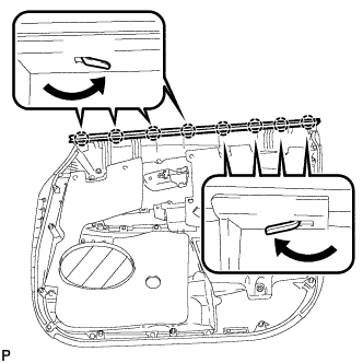
Engage the 8 claws and install the front door inner glass weatherstrip to the front door trim board sub-assembly as shown in the illustration.
-
-
INSTALL FRONT DOOR INSIDE HANDLE SUB-ASSEMBLY
-
Connect the front door lock remote control cable assembly and front door inside locking cable assembly to the front door inside handle.
-
Engage the 2 claws and install the front door inside handle sub-assembly to the rear door trim board sub-assembly.
-
-
INSTALL FRONT DOOR TRIM BOARD SUB-ASSEMBLY
-
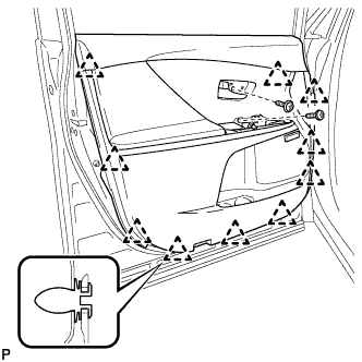
Engage the 10 clips and install the front door trim board sub-assembly.
-
Install the 2 screws.
-
-
INSTALL COURTESY LIGHT ASSEMBLY
-
Connect the connector.
-
Engage the claw to install the courtesy light assembly.
-
-
INSTALL POWER WINDOW REGULATOR MASTER SWITCH ASSEMBLY WITH FRONT DOOR ARMREST BASE PANEL (for Driver Side)
-
Connect the connector.
-
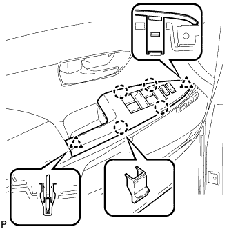
Engage the 2 clips and 4 claws, and install the power window regulator master switch assembly with front door armrest base panel.
-
-
INSTALL POWER WINDOW REGULATOR SWITCH ASSEMBLY WITH FRONT DOOR ARMREST BASE PANEL (for Front Passenger Side)
-
Connect the connector.
-
Engage the 2 clips and 4 claws, and install the power window regulator switch assembly with front door armrest base panel.
-
-
INSTALL FRONT DOOR INSIDE HANDLE BEZEL PLUG
-
Engage the 3 claws and install the front door inside handle bezel plug.
-
-
CONNECT CABLE TO NEGATIVE BATTERY TERMINAL
Note
When disconnecting the cable, some systems need to be initialized after the cable is reconnected Click here.
-
INITIALIZE POWER WINDOW CONTROL SYSTEM
-
INSPECT SRS WARNING LIGHT