OUTER REAR VIEW MIRROR INSPECTION

-
INSPECT OUTER REAR VIEW MIRROR ASSEMBLY RH
-
Check the operation of the mirror surface.
-
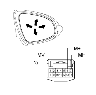
Text in Illustration *a Component without harness connected
(Outer Rear View Mirror Assembly RH)
Disconnect the outer rear view mirror assembly RH connector.
-
Apply battery voltage and check the operation of the mirror.
OK Measurement Condition Specified Condition Battery positive (+) → Terminal 5 (MV)
Battery negative (-) → Terminal 6 (M+)
Turns upward Battery positive (+) → Terminal 6 (M+)
Battery negative (-) → Terminal 5 (MV)
Turns downward Battery positive (+) → Terminal 7 (MH)
Battery negative (-) → Terminal 6 (M+)
Turns left Battery positive (+) → Terminal 6 (M+)
Battery negative (-) → Terminal 7 (MH)
Turns right If the result is not as specified, replace the outer rear view mirror assembly RH.
-
-
Check the operation of the mirror heater.
-
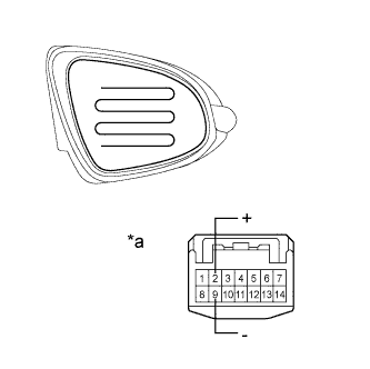
Text in Illustration *a Component without harness connected
(Outer Rear View Mirror Assembly RH)
Disconnect the outer rear view mirror assembly RH connector.
-
Measure the resistance according to the value(s) in the table below.
Standard Resistance Tester Connection Condition Specified Condition 2 (+) - 9 (-) 25°C (75°F) 7.6 to 11.4 Ω If the result is not as specified, replace the outer rear view mirror assembly RH.
-
Connect the cable from the positive (+) terminal to terminal 2 and the negative battery (-) terminal to terminal 9, then check that the mirror becomes warm.
Tech Tips
It takes a short time for the mirror to become warm.
OK Mirror becomes warm. If the result is not as specified, replace the outer rear view mirror assembly RH.
-
-
-
INSPECT OUTER REAR VIEW MIRROR ASSEMBLY LH
-
Check the operation of the mirror surface.
-

Text in Illustration *a Component without harness connected
(Outer Rear View Mirror Assembly LH)
Disconnect the outer rear view mirror assembly LH connector.
-
Apply battery voltage and check the operation of the mirror.
OK Measurement Condition Specified Condition Battery positive (+) → Terminal 5 (MV)
Battery negative (-) → Terminal 6 (M+)
Turns upward Battery positive (+) → Terminal 6 (M+)
Battery negative (-) → Terminal 5 (MV)
Turns downward Battery positive (+) → Terminal 7 (MH)
Battery negative (-) → Terminal 6 (M+)
Turns left Battery positive (+) → Terminal 6 (M+)
Battery negative (-) → Terminal 7 (MH)
Turns right If the result is not as specified, replace the outer rear view mirror assembly LH.
-
-
Check the operation of the mirror heater.
-
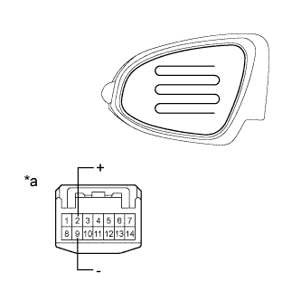
Text in Illustration *a Component without harness connected
(Outer Rear View Mirror Assembly LH)
Disconnect the outer rear view mirror assembly LH connector.
-
Measure the resistance according to the value(s) in the table below.
Standard Resistance Tester Connection Condition Specified Condition 2 (+) - 9 (-) 25°C (75°F) 7.6 to 11.4 Ω If the result is not as specified, replace the outer rear view mirror assembly LH.
-
Connect the cable from the positive (+) terminal to terminal 2 and the negative battery (-) terminal to terminal 8, then check that the mirror becomes warm.
Tech Tips
It takes a short time for the mirror to become warm.
OK Mirror becomes warm. If the result is not as specified, replace the outer rear view mirror assembly LH.
-
-