OUTER REAR VIEW MIRROR REMOVAL

-
PRECAUTION
Note
After turning the ignition switch off, waiting time may be required before disconnecting the cable from the negative (-) battery terminal. Therefore, make sure to read the disconnecting the cable from the negative (- ) battery terminal notices before proceeding with work Click here.
-
DISCONNECT CABLE FROM NEGATIVE BATTERY TERMINAL
CAUTION:
Wait at least 90 seconds after disconnecting the cable from the negative (-) battery terminal to disable the SRS system Click here.
Note
When disconnecting the cable, some systems need to be initialized after the cable is reconnected Click here.
-
REMOVE FRONT DOOR INSIDE HANDLE BEZEL PLUG
-

Using a moulding remover, disengage the 3 claws and remove the front door inside handle bezel plug.
-
-
REMOVE POWER WINDOW REGULATOR MASTER SWITCH ASSEMBLY WITH FRONT DOOR ARMREST BASE PANEL (for Driver Side)
-

Using a moulding remover, disengage the 2 clips and 4 claws.
-
Disconnect the connector and remove the power window regulator master switch assembly with front door armrest base panel.
-
-
REMOVE POWER WINDOW REGULATOR SWITCH ASSEMBLY WITH FRONT DOOR ARMREST BASE PANEL (for Front Passenger Side)
-

Using a moulding remover, disengage the 2 clips and 4 claws.
-
Disconnect the connector and remove the power window regulator switch assembly with front door armrest base panel.
-
-
REMOVE COURTESY LIGHT ASSEMBLY
-

Text in Illustration *1 Protective Tape Using a screwdriver wrapped with protective tape, disengage the claw.
-
Disconnect the connector and remove the courtesy light assembly.
-
-
REMOVE FRONT DOOR TRIM BOARD SUB-ASSEMBLY
-

Remove the 2 screws.
-
Using a clip remover, disengage the 10 clips.
-
Pull out the front door trim board sub-assembly in the direction indicated by the arrow as shown in the illustration.
-
Raise the front door trim board sub-assembly and remove the front door trim board sub-assembly together with the front door inner glass weatherstrip.
-
Disengage the 2 claws and disconnect the front door inside handle sub-assembly.
-
-
REMOVE FRONT DOOR INSIDE HANDLE SUB-ASSEMBLY
-

Disconnect the front door lock remote control cable and front door inside locking cable, and remove the front door inside handle sub-assembly.
-
-
REMOVE DOOR SIDE AIRBAG SENSOR
-
Check that the ignition switch is off.
-
Check that the cable is disconnected from the negative (-) battery terminal.
CAUTION:
Wait at least 90 seconds after disconnecting the cable from the negative (-) battery terminal to disable the SRS system.
-
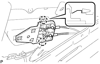
Disconnect the connector.
Note
When disconnecting the airbag connector, take care not to damage the airbag wire harness.
-
Push down the white housing lock and slide the yellow CPA. (At this time, the connector cannot be disconnected yet.)
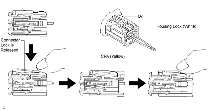
-
Push down the white housing lock again and disconnect the connector.
Tech Tips
Do not push down part (A) shown in the illustration when disconnecting.
-
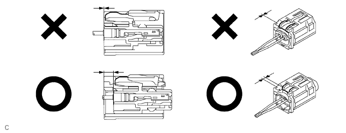
After disconnecting the connector, check that the position of the white housing lock is correct as shown in the illustration.
-
-
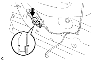
Remove the bolt and door side airbag sensor.
Note
Loosen the bolt while holding the door side airbag sensor because the door side airbag sensor pin (stopper) is easily damaged.
-
-
REMOVE OUTER MIRROR CONTROL ECU ASSEMBLY
-
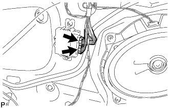
Disconnect the 2 connectors.
-
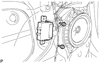
Remove the 2 screws and outer mirror control ECU assembly.
-
-
REMOVE FRONT DOOR SERVICE HOLE COVER
-

Disengage the clamp.
-
Remove the bolt.
-
Remove the front door service hole cover.
Tech Tips
Remove any remaining butyl tape from the door.
-
-
REMOVE OUTER REAR VIEW MIRROR ASSEMBLY
-
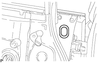
Remove the hole plug.
-
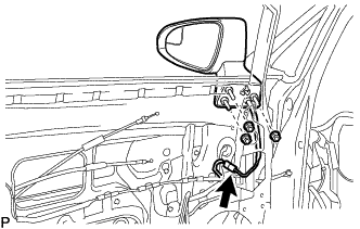
Disconnect the connector.
-
Remove the 3 nuts.
-
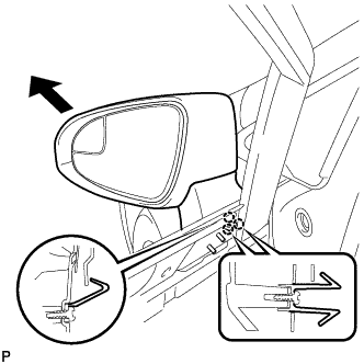
Disengage the 3 claws and remove the outer rear view mirror assembly as shown in the illustration.
-