POWER BACK DOOR SYSTEM TERMINALS OF ECU

-
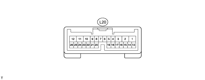
CHECK POWER BACK DOOR ECU (POWER BACK DOOR MOTOR UNIT)
-
Disconnect the L20 ECU connector.
-
Measure the voltage and resistance according to the value(s) in the table below.
Tester Connection Wiring Color Terminal Description Condition Specified Condition L20-10 (ECUB) - Body ground P - Body ground Battery power supply Always 11 to 14 V L20-12 (B) - Body ground LG - Body ground Battery power supply Always 11 to 14 V L20-8 (IG) - Body ground SB - Body ground IG power supply Engine switch on (IG) 11 to 14 V L20-8 (IG) - Body ground SB - Body ground IG power supply Engine switch off Below 1 V L20-17 (MSW) - Body ground R - Body ground Power back door main switch signal Power back door main switch not pushed Below 1 Ω L20-17 (MSW) - Body ground R - Body ground Power back door main switch signal Power back door main switch pushed 10 kΩ or higher L20-4 (DS1) - Body ground L - Body ground Power back door closer switch signal Power back door closer switch on Below 1 Ω L20-4 (DS1) - Body ground L - Body ground Power back door closer switch signal Power back door closer switch off 10 kΩ or higher L20-15 (OSL) - L20-14 (OSE) Y - V Power back door touch sensor LH signal Power back door touch sensor LH not pressed 950 to 1050 Ω L20-15 (OSL) - L20-14 (OSE) Y - V Power back door touch sensor LH signal Back door touch sensor LH pressed Below 100 Ω L20-13 (OSR) - L20-14 (OSE) R - V Power back door touch sensor RH signal Back door touch sensor RH not pressed 950 to 1050 Ω L20-13 (OSR) - L20-14 (OSE) R - V Power back door touch sensor RH signal Power back door touch sensor RH pressed Below 100 Ω L20-11 (GND) - Body ground W-B - Body ground Ground Always Below 1 Ω If the result is not as specified, there may be a malfunction on the wire harness side.
-
Reconnect the L20 ECU connector.
-
Initialize the power back door system Click here.
-
Measure the voltage according to the value(s) in the table below.
Tester Connection Wiring Color Terminal Description Condition Specified Condition L20-17 (MSW) - Body ground R - Body ground Power back door main switch signal Power back door main switch not pushed Below 1 V L20-17 (MSW) - Body ground R - Body ground Power back door main switch signal Power back door main switch pushed Pulse generation L20-26 (BZR+) - Body ground SB - Body ground Power back door warning buzzer signal input Back door warning buzzer sounding Pulse generation L20-26 (BZR+) - Body ground SB - Body ground Power back door warning buzzer signal input Back door warning buzzer stopped Below 1 V L20-2 (DC+) - L20-1 (DC-) L - G Power back door lock motor signal Back door lock motor operating 11 to 14 V L20-2 (DC+) - L20-1 (DC-) L - G Power back door lock motor signal Back door lock motor stopped Below 1 V L20-4 (DS1) - Body ground L - Body ground Power back door closer switch signal Power back door closer switch on Below 1 V L20-4 (DS1) - Body ground L - Body ground Power back door closer switch signal Power back door closer switch off Pulse generation L20-15 (OSL) - L20-14 (OSE) Y - V Power back door touch sensor LH signal Power back door touch sensor LH not pressed 4 to 6 V L20-15 (OSL) - L20-14 (OSE) Y - V Power back door touch sensor LH signal Back door touch sensor LH pressed Below 1 V L20-13 (OSR) - L20-14 (OSE) R - V Power back door touch sensor RH signal Back door touch sensor RH not pressed 4 to 6 V L20-13 (OSR) - L20-14 (OSE) R - V Power back door touch sensor RH signal Power back door touch sensor RH pressed Below 1 V If the result is not as specified, the ECU may have a malfunction.
-
-
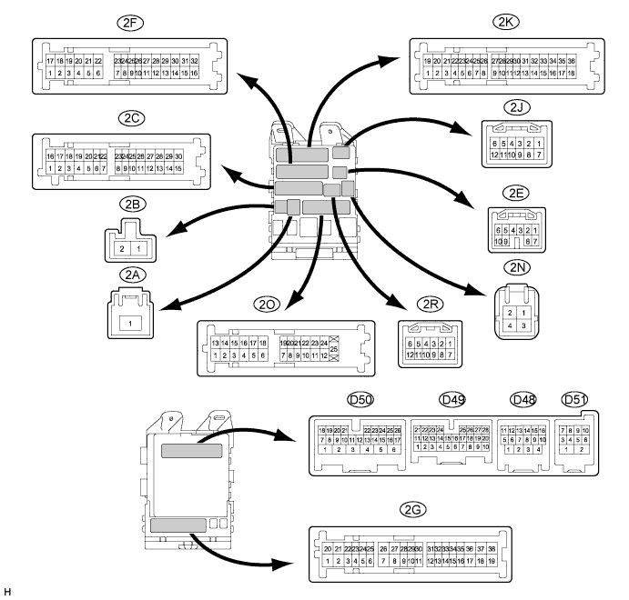
CHECK MAIN BODY ECU (DRIVER SIDE JUNCTION BLOCK ASSEMBLY)
-
Disconnect the D49 and 2F connectors.
-
Measure the resistance according to the value(s) in the table below.
Tester Connection Wiring Color Terminal Description Condition Specified Condition D49-2 (BDSU) - Body ground GR - Body ground Back door opener switch signal circuit Back door opener switch on Below 1 Ω D49-2 (BDSU) - Body ground GR - Body ground Back door opener switch signal circuit Back door opener switch off 10 kΩ or higher D49-26 (PBDS) - Body ground BR - Body ground Power back door open / close switch signal circuit Power back door open / close switch on Below 1 Ω D49-26 (PBDS) - Body ground BR - Body ground Power back door open / close switch signal circuit Power back door open / close switch off 10 kΩ or higher 2F-16 (GND1) - Body ground W-B - Body ground Ground Always Below 1 Ω If the result is not as specified, there may be a malfunction on the wire harness side.
-
Reconnect the D49 and 2F connectors.
-
Measure the voltage according to the value(s) in the table below.
Tester Connection Wiring Color Terminal Description Condition Specified Condition D49-26 (PBDS) - Body ground BR - Body ground Power back door control switch signal Power back door control switch on Below 1 V D49-26 (PBDS) - Body ground BR - Body ground Power back door control switch signal Power back door control switch off Pulse generation D49-2 (BDSU) - Body ground GR - Body ground Back door opener switch signal Back door opener switch on Below 1 V D49-2 (BDSU) - Body ground GR - Body ground Back door opener switch signal Back door opener switch off Pulse generation If the result is not as specified, the ECU may have a malfunction.
-