BACK DOOR CLOSER SYSTEM Back Door cannot be Opened
DESCRIPTION
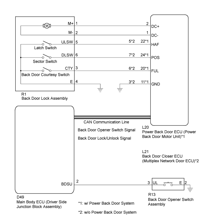
When the back door cannot be opened, one of the following may be malfunctioning: 1) power back door ECU (power back door motor unit)*1 or back door closer ECU (multiplex network door ECU)*2, 2) back door lock assembly, 3) back door opener switch assembly, or 4) main body ECU (driver side junction block assembly).
-
*1: w/ Power Back Door System
-
*2: w/o Power Back Door System
WIRING DIAGRAM
INSPECTION PROCEDURE
Note
The back door closer system uses CAN communication. First, follow "How to Proceed with Troubleshooting" and at step "Check Communication Function of CAN Communication System", confirm that there is no malfunction in the CAN communication system. After confirming that B2250 or B2251 is not output, proceed with troubleshooting.
PROCEDURE
-
READ VALUE USING GTS
-
Connect the GTS to the DLC3.
-
Turn the ignition switch to ON.
-
Turn the GTS on.
-
Enter the following menus: Body Electrical / Main Body / Data List.
-
Check if the back door lock functions properly.
Main Body (Main Body ECU (Driver Side Junction Block Assembly)) Tester Display Measurement Item/Range Normal Condition Diagnostic Note Back Door Open Back door lock / Permit or Prohibit Permit: Back door unlocked
Prohibit: Back door locked
- OK The back door functions as specified in the normal condition column.
NG 
REPLACE MAIN BODY ECU (DRIVER SIDE JUNCTION BLOCK ASSEMBLY) Click here
OK 
-
-
READ VALUE USING GTS
-
Connect the GTS to the DLC3.
-
Turn the ignition switch to ON.
-
Turn the GTS on.
-
Enter the following menus: Body Electrical / Back Door / Data List.
-
Check if the back door lock functions properly.
Back Door (Power Back Door ECU*1 or Back Door Closer ECU*2) Tester Display Measurement Item/Range Normal Condition Diagnostic Note Door Lock Status Back door lock condition signal / LOCK or UNLOCK LOCK: Back door locked
UNLOCK: Back door unlocked
-
-
*1: w/ Power Back Door System
-
*2: w/o Power Back Door System
OK The back door functions as specified in the normal condition column. Result Result Proceed to OK A NG (w/ Power Back Door ECU) B NG (w/o Power Back Door ECU) C -
B
REPLACE POWER BACK DOOR ECU (POWER BACK DOOR MOTOR UNIT) Click here
C
REPLACE BACK DOOR CLOSER ECU (MULTIPLEX NETWORK DOOR ECU)
A
-
-
READ VALUE USING GTS
-
Connect the GTS to the DLC3.
-
Turn the ignition switch to ON.
-
Turn the GTS on.
-
Enter the following menus: Body Electrical / Main Body / Data List.
-
Check if the switch functions properly.
Main Body (Main Body ECU (Driver Side Junction Block Assembly)) Tester Display Measurement Item/Range Normal Condition Diagnostic Note Back Door Open Handle SW Back door opener switch / ON or OFF ON: Back door opener switch pushed
OFF: Back door opener switch not pushed
- OK The back door opener switch functions as specified in the normal condition column.
NG 
INSPECT BACK DOOR OPENER SWITCH ASSEMBLY Click here
OK
-
-
INSPECT BACK DOOR LOCK ASSEMBLY
-
Remove the back door lock assembly Click here.
-
Apply battery voltage and check the operation of the door lock motor.
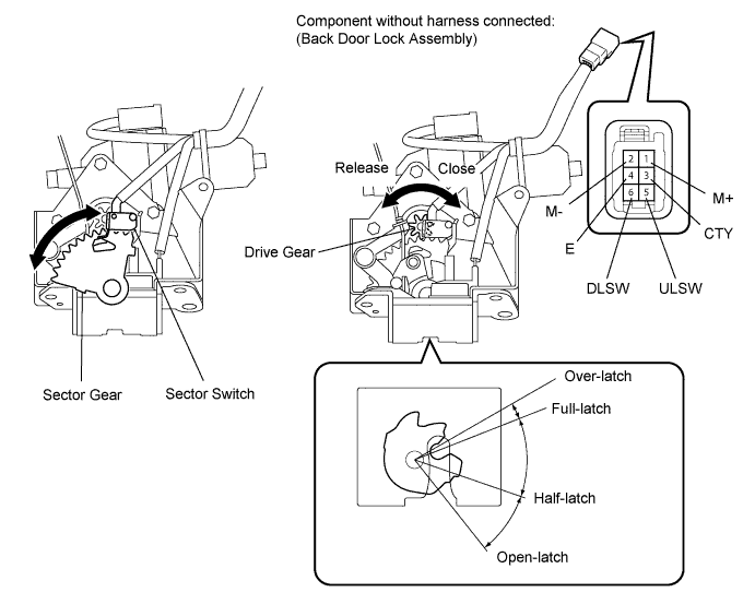
OK Measurement Condition Specified Condition Battery positive (+) → Terminal 1 (M+)
Battery negative (-) → Terminal 2 (M-)
Latch turns to full-latch position Battery positive (+) → Terminal 2 (M-)
Battery negative (-) → Terminal 1 (M+)
Latch turns to open-latch position -
Measure the resistance according to the value(s) in the table below.
Standard Resistance Latch Switch Tester Connection Condition Specified Condition 5 (ULSW) - 4 (E) Open-latch Below 1 Ω 5 (ULSW) - 4 (E) Half-latch 10 kΩ or higher 5 (ULSW) - 4 (E) Full-latch 10 kΩ or higher 5 (ULSW) - 4 (E) Over-latch Below 1 Ω Sector Switch Tester Connection Condition Specified Condition 6 (DLSW) - 4 (E) Sector gear in neutral position (Sector switch on) Below 1 Ω 6 (DLSW) - 4 (E) Sector gear not in neutral position (Sector switch off) 10 kΩ or higher Back Door Courtesy Switch Tester Connection Condition Specified Condition 3 (CTY) - 4 (E) Open-latch Below 1 Ω 3 (CTY) - 4 (E) Half-latch Below 1 Ω 3 (CTY) - 4 (E) Full-latch 10 kΩ or higher 3 (CTY) - 4 (E) Over-latch 10 kΩ or higher
NG
REPLACE BACK DOOR LOCK ASSEMBLY Click here
OK
-
-
CHECK HARNESS AND CONNECTOR (BACK DOOR LOCK ASSEMBLY - POWER BACK DOOR ECU OR BACK DOOR CLOSER ECU)
-
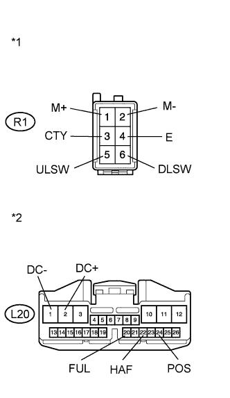
Text in Illustration *1 Front view of wire harness connector
(to Back Door Lock Assembly)
*2 Front view of wire harness connector
(to Power Back Door ECU)
w/ Power Back Door System
-
Disconnect the R1 back door lock assembly connector and L20 power back door ECU connector.
-
Measure the resistance according to the value(s) in the table below.
Standard Resistance Tester Connection Condition Specified Condition R1-1 (M+) - L20-2 (DC+) Always Below 1 Ω R1-2 (M-) - L20-1 (DC-) Always Below 1 Ω R1-5 (ULSW) - L20-22 (HAF) Always Below 1 Ω R1-6 (DLSW) - L20-24 (POS) Always Below 1 Ω R1-3 (CTY) - L20-20 (FUL) Always Below 1 Ω R1-4 (E) - Body ground Always Below 1 Ω R1-1 (M+) - Body ground Always 10 kΩ or higher R1-2 (M-) - Body ground Always 10 kΩ or higher R1-5 (ULSW) - Body ground Always 10 kΩ or higher R1-6 (DLSW) - Body ground Always 10 kΩ or higher R1-3 (CTY) - Body ground Always 10 kΩ or higher
-
-
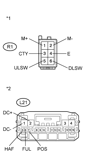
Text in Illustration *1 Front view of wire harness connector
(to Back Door Lock Assembly)
*2 Front view of wire harness connector
(to Back Door Closer ECU)
w/o Power Back Door System
-
Disconnect the R1 back door lock assembly connector and L21 back door closer ECU connector.
-
Measure the resistance according to the value(s) in the table below.
Standard Resistance Tester Connection Condition Specified Condition R1-1 (M+) - L21-2 (DC+) Always Below 1 Ω R1-2 (M-) - L21-1 (DC-) Always Below 1 Ω R1-3 (CTY) - L21-6 (FUL) Always Below 1 Ω R1-5 (ULSW) - L21-5 (HAF) Always Below 1 Ω R1-6 (DLSW) - L21-7 (POS) Always Below 1 Ω R1-4 (E) - Body ground Always Below 1 Ω R1-1 (M+) - Body ground Always 10 kΩ or higher R1-2 (M-) - Body ground Always 10 kΩ or higher R1-3 (CTY) - Body ground Always 10 kΩ or higher R1-5 (ULSW) - Body ground Always 10 kΩ or higher R1-6 (DLSW) - Body ground Always 10 kΩ or higher
Result Result Proceed to NG A OK (w/ Power Back Door System) B OK (w/o Power Back Door System) C -
B
REPLACE POWER BACK DOOR ECU (POWER BACK DOOR MOTOR UNIT) Click here
C
REPLACE BACK DOOR CLOSER ECU (MULTIPLEX NETWORK DOOR ECU)
A 
REPAIR OR REPLACE HARNESS OR CONNECTOR
-
-
INSPECT BACK DOOR OPENER SWITCH ASSEMBLY
-
Remove the back door opener switch assembly Click here.
-
Measure the resistance according to the value(s) in the table below.
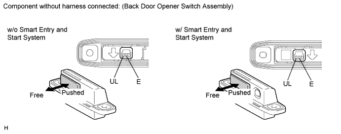
Standard Resistance Tester Connection Condition Specified Condition 2 (E) - 3 (UL) Back door opener switch not pushed (off) 10 kΩ or higher 2 (E) - 3 (UL) Back door opener switch pushed (on) Below 1 Ω
NG
REPLACE BACK DOOR OPENER SWITCH ASSEMBLY Click here
OK
-
-
CHECK HARNESS AND CONNECTOR (BACK DOOR OPENER SWITCH ASSEMBLY - MAIN BODY ECU)
-
Disconnect the R13 back door opener switch assembly connector and D49 main body ECU connector.
-
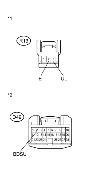
Text in Illustration *1 Front view of wire harness connector
(to Back Door Opener Switch Assembly)
*2 Front view of wire harness connector
(to Main Body ECU)
Measure the resistance according to the value(s) in the table below.
Standard Resistance Tester Connection Condition Specified Condition R13-3 (UL) - D49-2 (BDSU) Always Below 1 Ω R13-2 (E) - Body ground Always Below 1 Ω R13-3 (UL) - Body ground Always 10 kΩ or higher
NG
REPAIR OR REPLACE HARNESS OR CONNECTOR
OK
REPLACE MAIN BODY ECU (DRIVER SIDE JUNCTION BLOCK ASSEMBLY) Click here
-