BACK DOOR CLOSER SYSTEM Back Door Closer does not Operate
DESCRIPTION
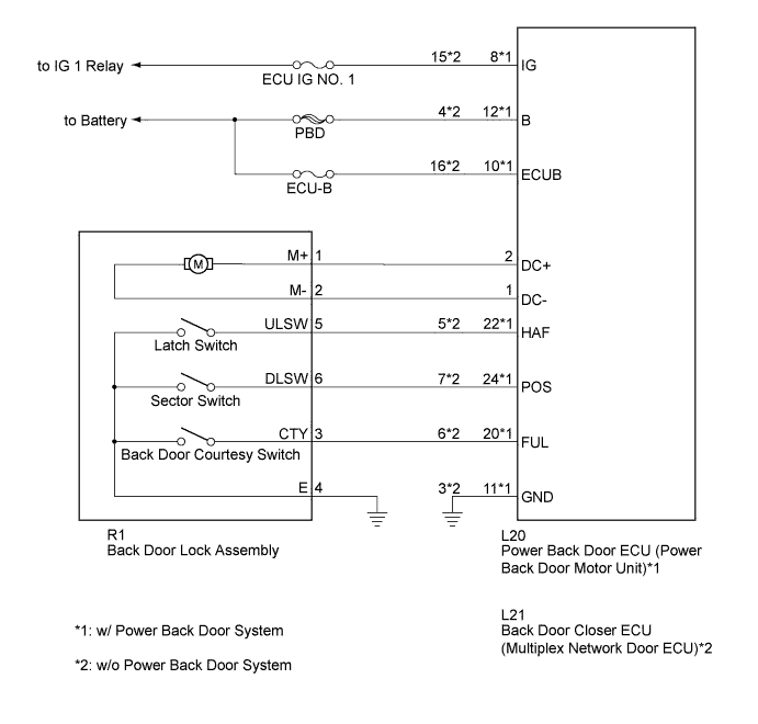
When the back door closer does not operate, one of the following may be the cause: 1) improper fit of the back door, or a foreign matter is stuck in the back door or 2) initialization of the power back door ECU (power back door motor unit)*1, or a malfunction in the 3) power back door ECU (power back door motor unit)*1 or back door closer ECU (multiplex network door ECU)*2 power source circuit, 4) back door lock circuit, or 5) power back door ECU (power back door motor unit)*1 or back door closer ECU (multiplex network door ECU)*2.
-
*1: w/ Power Back Door System
-
*2: w/o Power Back Door System
WIRING DIAGRAM
INSPECTION PROCEDURE
Note
Inspect fuses for circuits related to this system before performing the following inspection procedure.
PROCEDURE
-
CHECK BACK DOOR LOCK FUNCTION
-
Check if the back door is fully closed by hand.
Result Result Proceed to OK (w/ Power Back Door System) A OK (w/o Power Back Door System) B NG C
B 
CHECK DTC OUTPUT Click here
C 
IMPROPER FIT OF BACK DOOR, OR A FOREIGN MATTER IS STUCK IN BACK DOOR
A 
-
-
INITIALIZE POWER BACK DOOR ECU
-
Perform the initialization of the power back door ECU (power back door motor unit) Click here.
NEXT
-
-
CHECK BACK DOOR CLOSER SYSTEM
-
Check back door closer system operation.
OK Back door closer system operates normally.
NG
READ VALUE USING GTS (POWER BACK DOOR TOUCH SENSOR) Click here
OK 
END
-
-
READ VALUE USING GTS (POWER BACK DOOR TOUCH SENSOR)
-
Connect the GTS to the DLC3.
-
Turn the ignition switch to ON.
-
Turn the GTS on.
-
Enter the following menus: Body Electrical / Back Door / Data List.
-
Check the Data List to determine if the power back door touch sensor functions properly.
Back Door (Power Back Door ECU) Tester Display Measurement Item/Range Normal Condition Diagnostic Note PBD Touch Sensor (Right) Power back door touch sensor RH signal / ON or OFF ON: Power back door touch sensor RH pressed
OFF: Power back door touch sensor RH not pressed
- PBD Touch Sensor (Left) Power back door touch sensor LH signal / ON or OFF ON: Power back door touch sensor LH pressed
OFF: Power back door touch sensor LH not pressed
- OK The power back door sensors function as specified in the normal condition column.
NG
GO TO OTHER FLOW CHART (TOUCH SENSOR CIRCUIT) Click here
OK
-
-
CHECK DTC OUTPUT
-
Connect the GTS to the DLC3.
-
Turn the ignition switch to ON.
-
Turn the GTS on.
-
Enter the following menus: Body Electrical / Back Door / DTC.
-
Check for DTCs.
Result Result Proceed to DTC is not output A B2250 is output B B2251 is output C
B
GO TO DTC CHART (B2250) Click here
C
GO TO DTC CHART (B2251) Click here
A
-
-
CHECK HARNESS AND CONNECTOR (POWER SOURCE)
-
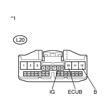
Text in Illustration *1 Front view of wire harness connector
(to Power Back Door ECU)
w/ Power Back Door System
-
Disconnect the L20 power back door ECU connector.
-
Measure the voltage according to the value(s) in the table below.
Standard Voltage Tester Connection Condition Specified Condition L20-8 (IG) - Body ground Ignition switch ON 11 to 14 V L20-10 (ECUB) - Body ground Always 11 to 14 V L20-12 (B) - Body ground Always 11 to 14 V
-
-
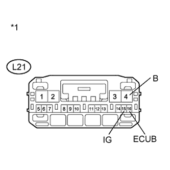
Text in Illustration *1 Front view of wire harness connector
(to Back Door Closer ECU)
w/o Power Back Door System
-
Disconnect the L21 back door closer ECU connector.
-
Measure the voltage according to the value(s) in the table below.
Standard Voltage Tester Connection Condition Specified Condition L21-4 (B) - Body ground Always 11 to 14 V L21-16 (ECUB) - Body ground Always 11 to 14 V L21-15 (IG) - Body ground Ignition switch ON 11 to 14 V
-
NG
REPAIR OR REPLACE HARNESS OR CONNECTOR
OK
-
-
CHECK HARNESS AND CONNECTOR (BODY GROUND)
-
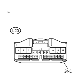
Text in Illustration *1 Front view of wire harness connector
(to Power Back Door ECU)
w/ Power Back Door System
-
Disconnect the L20 power back door ECU connector.
-
Measure the resistance according to the value(s) in the table below.
Standard Resistance Tester Connection Condition Specified Condition L20-11 (GND) - Body ground Always Below 1 Ω
-
-
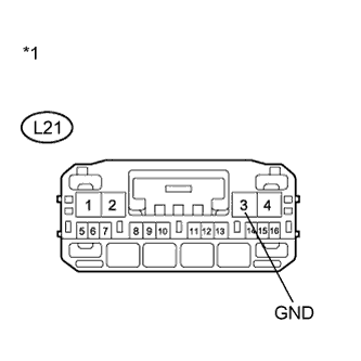
Text in Illustration *1 Front view of wire harness connector
(to Back Door Closer ECU)
w/o Power Back Door System
-
Disconnect the L21 back door closer ECU connector.
-
Measure the resistance according to the value(s) in the table below.
Standard Resistance Tester Connection Condition Specified Condition L21-3 (GND) - Body ground Always Below 1 Ω
-
NG
REPAIR OR REPLACE HARNESS OR CONNECTOR
OK
-
-
INSPECT BACK DOOR LOCK ASSEMBLY
-
Remove the back door lock assembly Click here.
-
Apply battery voltage and check the operation of the door lock motor.
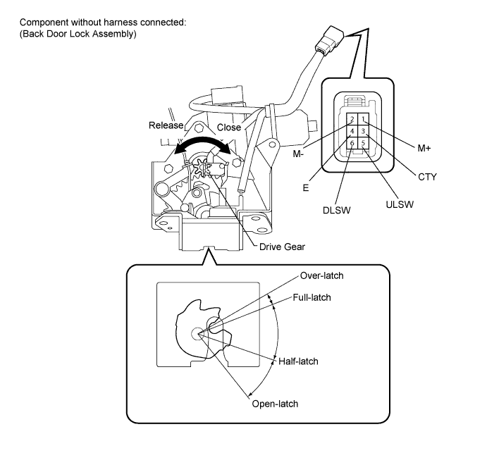
OK Measurement Condition Specified Condition Battery positive (+) → Terminal 1 (M+)
Battery negative (-) → Terminal 2 (M-)
Latch turns to full-latch position Battery positive (+) → Terminal 2 (M-)
Battery negative (-) → Terminal 1 (M+)
Latch turns to open-latch position -
Measure the resistance according to the value(s) in the table below.
Standard Resistance Latch Switch Tester Connection Condition Specified Condition 5 (ULSW) - 4 (E) Open-latch Below 1 Ω 5 (ULSW) - 4 (E) Half-latch 10 kΩ or higher 5 (ULSW) - 4 (E) Full-latch 10 kΩ or higher 5 (ULSW) - 4 (E) Over-latch Below 1 Ω Back Door Courtesy Switch Tester Connection Condition Specified Condition 3 (CTY) - 4 (E) Open-latch Below 1 Ω 3 (CTY) - 4 (E) Half-latch Below 1 Ω 3 (CTY) - 4 (E) Full-latch 10 kΩ or higher 3 (CTY) - 4 (E) Over-latch 10 kΩ or higher
NG
REPLACE BACK DOOR LOCK ASSEMBLY Click here
OK
-
-
CHECK HARNESS AND CONNECTOR (BACK DOOR LOCK - POWER BACK DOOR ECU OR BACK DOOR CLOSER ECU)
-
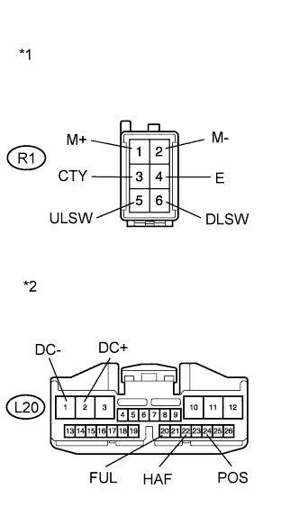
Text in Illustration *1 Front view of wire harness connector
(to Back Door Lock)
*2 Front view of wire harness connector
(to Power Back Door ECU)
w/ Power Back Door System
-
Disconnect the R1 back door lock assembly connector and L20 power back door ECU connector.
-
Measure the resistance according to the value(s) in the table below.
Standard Resistance Tester Connection Condition Specified Condition R1-1 (M+) - L20-2 (DC+) Always Below 1 Ω R1-2 (M-) - L20-1 (DC-) Always Below 1 Ω R1-5 (ULSW) - L20-22 (HAF) Always Below 1 Ω R1-6 (DLSW) - L20-24 (POS) Always Below 1 Ω R1-3 (CTY) - L20-20 (FUL) Always Below 1 Ω R1-4 (E) - Body ground Always Below 1 Ω R1-1 (M+) - Body ground Always 10 kΩ or higher R1-2 (M-) - Body ground Always 10 kΩ or higher R1-5 (ULSW) - Body ground Always 10 kΩ or higher R1-6 (DLSW) - Body ground Always 10 kΩ or higher R1-3 (CTY) - Body ground Always 10 kΩ or higher
-
-
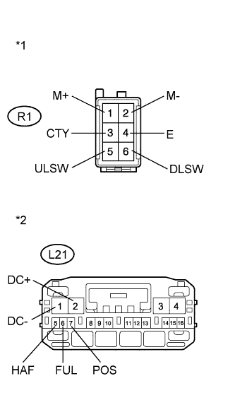
Text in Illustration *1 Front view of wire harness connector
(to Back Door Lock)
*2 Front view of wire harness connector
(to Back Door Closer ECU)
w/o Power Back Door System
-
Disconnect the R1 back door lock assembly connector and L21 back door closer ECU connector.
-
Measure the resistance according to the value(s) in the table below.
Standard Resistance Tester Connection Condition Specified Condition R1-1 (M+) - L21-2 (DC+) Always Below 1 Ω R1-2 (M-) - L21-1 (DC-) Always Below 1 Ω R1-3 (CTY) - L21-6 (FUL) Always Below 1 Ω R1-5 (ULSW) - L21-5 (HAF) Always Below 1 Ω R1-6 (DLSW) - L21-7 (POS) Always Below 1 Ω R1-4 (E) - Body ground Always Below 1 Ω R1-1 (M+) - Body ground Always 10 kΩ or higher R1-2 (M-) - Body ground Always 10 kΩ or higher R1-3 (CTY) - Body ground Always 10 kΩ or higher R1-5 (ULSW) - Body ground Always 10 kΩ or higher R1-6 (DLSW) - Body ground Always 10 kΩ or higher
Result Result Proceed to NG A OK (w/ Power Back Door System) B OK (w/o Power Back Door System) C -
B
REPLACE POWER BACK DOOR ECU (POWER BACK DOOR MOTOR UNIT) Click here
C
REPLACE BACK DOOR CLOSER ECU (MULTIPLEX NETWORK DOOR ECU)
A
REPAIR OR REPLACE HARNESS OR CONNECTOR
-