BACK DOOR CLOSER SYSTEM, Diagnostic DTC:B2250

| DTC Code | DTC Name |
|---|---|
| B2250 | Back Door Closer Operation Malfunction |
DESCRIPTION
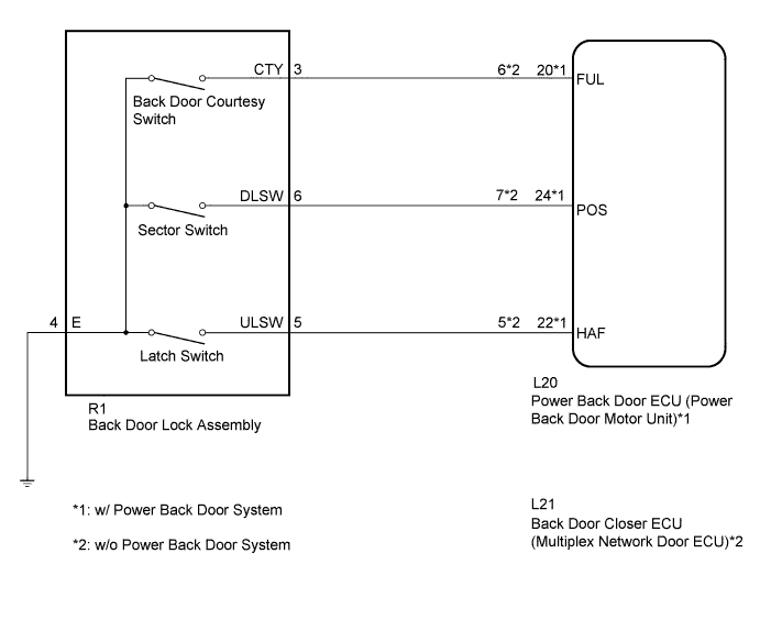
The power back door ECU (power back door motor unit)*1 or back door closer ECU (multiplex network door ECU)*2 receives signals from the latch switch, sector switch and back door courtesy switch, which are built into the back door lock assembly. Based on these switch signals, the latch position of the back door lock assembly is determined.
| DTC No. | DTC Detection Condition | Trouble Area |
|---|---|---|
| B2250 | While the back door closer is operating, a malfunction is detected in position information from the sector switch within a specified amount of time. |
|
-
*1: w/ Power Back Door System
-
*2: w/o Power Back Door System
WIRING DIAGRAM
INSPECTION PROCEDURE
PROCEDURE
-
INSPECT BACK DOOR LOCK ASSEMBLY (SECTOR SWITCH)
-
Remove the back door lock assembly Click here.
-
Measure the resistance according to the value(s) in the table below.
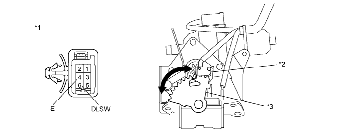
Standard Resistance Sector Switch Tester Connection Condition Specified Condition 6 (DLSW) - 4 (E) Sector gear in neutral position (Sector switch on) Below 1 Ω 6 (DLSW) - 4 (E) Sector gear not in neutral position (Sector switch off) 10 kΩ or higher Text in Illustration *1 Component without harness connected
(Back Door Lock Assembly)
*3 Sector Gear *2 Sector Switch - -
NG 
REPLACE BACK DOOR LOCK ASSEMBLY Click here
OK 
-
-
CHECK HARNESS AND CONNECTOR (BACK DOOR LOCK - POWER BACK DOOR ECU OR BACK DOOR CLOSER ECU)
-
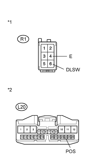
Text in Illustration *1 Front view of wire harness connector
(to Back Door Lock Assembly)
*2 Front view of wire harness connector
(to Power Back Door ECU)
w/ Power Back Door System
-
Disconnect the R1 back door lock assembly connector and L20 power back door ECU connector.
-
Measure the resistance according to the value(s) in the table below.
Standard Resistance Tester Connection Condition Specified Condition R1-6 (DLSW) - L20-24 (POS) Always Below 1 Ω R1-4 (E) - Body ground Always Below 1 Ω R1-6 (DLSW) - Body ground Always 10 kΩ or higher
-
-
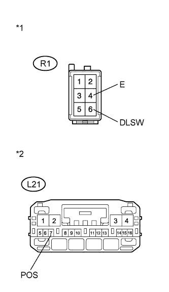
Text in Illustration *1 Front view of wire harness connector
(to Back Door Lock Assembly)
*2 Front view of wire harness connector
(to Back Door Closer ECU)
w/o Power Back Door System
-
Disconnect the R1 back door lock assembly connector and L21 back door closer ECU connector.
-
Measure the resistance according to the value(s) in the table below.
Standard Resistance Tester Connection Condition Specified Condition R1-6 (DLSW) - L21-7 (POS) Always Below 1 Ω R1-4 (E) - Body ground Always Below 1 Ω R1-6 (DLSW) - Body ground Always 10 kΩ or higher
Result Result Proceed to NG A OK (w/ Power Back Door System) B OK (w/o Power Back Door System) C -
B
REPLACE POWER BACK DOOR ECU (POWER BACK DOOR MOTOR UNIT) Click here
C
REPLACE BACK DOOR CLOSER ECU (MULTIPLEX NETWORK DOOR ECU)
A 
REPAIR OR REPLACE HARNESS OR CONNECTOR
-