HOOD LOCK CONTROL CABLE ASSEMBLY INSTALLATION

-
INSTALL HOOD LOCK CONTROL CABLE ASSEMBLY
-
Pass the hood lock control cable assembly into the engine compartment.
-
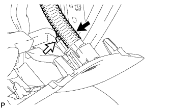
Pass the cable through the upper radiator support.
-
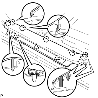
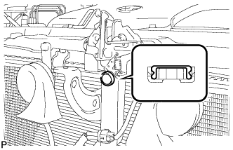
Engage each clamp shown in the illustration.
-
-
INSTALL LOWER NO. 1 INSTRUMENT PANEL FINISH PANEL
-
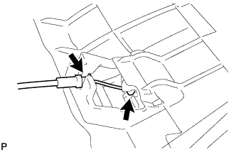
Connect the hood lock control cable.
-
Connect the aspirator duct and connector.
-
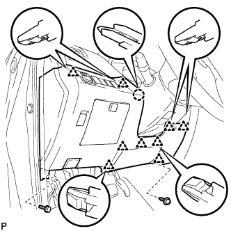
Connect the connectors.
-
Engage the claw and 9 clips.
-
Install the lower No. 1 instrument panel finish panel with the bolt <C> and screw <E> or <F>.
-
-
INSTALL COWL SIDE TRIM SUB-ASSEMBLY LH
-
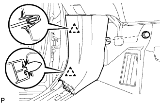
Engage the 2 clips to install the cowl side trim sub-assembly LH.
-
Install the clip.
-
-
INSTALL FRONT DOOR SCUFF PLATE LH
-
Engage the guide, 3 clips and the 7 claws to install the front door scuff plate LH.
-
-
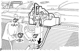
INSTALL HOOD LOCK ASSEMBLY (w/o Engine Hood Courtesy Switch)
-
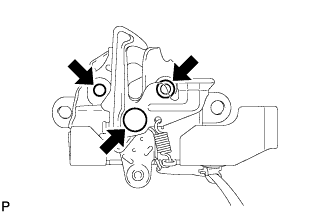
Apply MP grease to the sliding areas of the lock.
-
Connect the hood lock control cable.
-
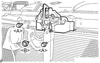
Install the hood lock assembly with the 3 bolts.
- Torque:
- <A> Centering Bolt
- 8.0 N*m { 82 kgf*cm, 71 in.*lbf }
- Torque:
- <A> Standard Bolt
- 7.5 N*m { 77 kgf*cm, 66 in.*lbf }
- Torque:
- <B>
- 8.0 N*m { 82 kgf*cm, 71 in.*lbf }
-
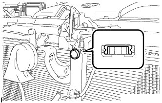
Install a new hood lock nut cap.
-
-
INSTALL HOOD LOCK ASSEMBLY (w/ Engine Hood Courtesy Switch)
-
Apply MP grease to the sliding areas of the lock.
-
Connect the hood lock control cable.
-
Install the hood lock assembly with the 3 bolts.
- Torque:
- <A> Centering Bolt
- 8.0 N*m { 82 kgf*cm, 71 in.*lbf }
- Torque:
- <A> Standard Bolt
- 7.5 N*m { 77 kgf*cm, 66 in.*lbf }
- Torque:
- <B>
- 8.0 N*m { 82 kgf*cm, 71 in.*lbf }
-
Connect the connector.
-
Install a new hood lock nut cap.
-
-
INSTALL LOW PITCHED HORN ASSEMBLY
-
Install the low pitched horn assembly with the bolt.
- Torque:
- 20 N*m { 204 kgf*cm, 15 ft.*lbf }
-
Connect the connector.
-
-
INSTALL RADIATOR GRILLE
-
Engage the 6 claws.
-
Install the 3 clips.
-
Install the radiator grille with the 2 bolts.
-
-
INSTALL COOL AIR INTAKE DUCT SEAL
-
Install the cool air intake duct seal with the 12 clips.
-
-
INSTALL FRONT FENDER LINER LH
-
Install the front fender liner LH with new grommet.
-
Install the 5 clips <A>.
-
Install the clip <B>.
-
Install the bolt and 6 clips.
-
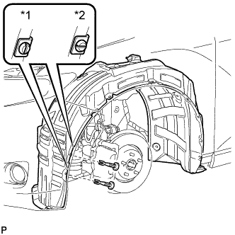
Text in Illustration *1 Correct *2 Incorrect Install the 2 pin hold clips.
Note
Insert the pin hold clip with the slot aligned vertically. Do not rotate the clip after inserting it. After installation, confirm that the slot is vertical.
-
-
INSTALL FRONT WHEEL LH
- Torque:
- 103 N*m { 1050 kgf*cm, 76 ft.*lbf }
-
INSTALL FRONT FENDER OUTSIDE MOULDING LH
-
Clean the vehicle body surface.
-
Using a heat light, heat the vehicle body surface.
-
Remove the double-sided tape from the vehicle body.
-
Wipe off any tape adhesive residue with cleaner.
-
-
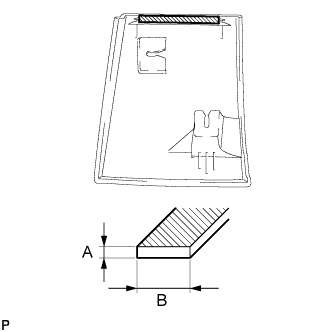
Clean the front fender outside moulding.
Dimension Measurement A 1.2 mm (0.0472 in.) B 6.0 mm (0.236 in.)
-
Using a heat light, heat the front fender outside moulding.
-
Remove the double-sided tape from the front fender outside moulding.
-
Wipe off any tape adhesive residue with cleaner.
-
Apply new double-sided tape to the front fender outside moulding.
-
-
Install 2 new clips (No. 1 outside moulding clip) to the front fender outside moulding.
-
Install the front fender outside moulding.
-
Using a heat light, heat the vehicle body and front fender outside moulding.
-
Remove the release paper from the front fender outside moulding.
Tech Tips
After removing the release paper, keep the exposed adhesive free from foreign matter.
-
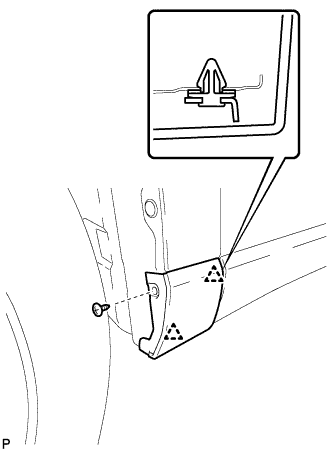
Engage the 2 clips and install the front fender outside moulding.
-
-
Install the screw.
-
-
INSPECT HOOD SUB-ASSEMBLY
-
Check that the clearance measurements of areas *1 through *4 are within each standard range.
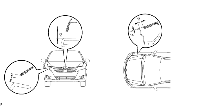
Standard Clearance Area Measurement Area Measurement *1 6.9 to 9.9 mm (0.272 to 0.390 in.) *3 2.8 to 5.8 mm (0.110 to 0.228 in.) *2 7.6 to 10.6 mm (0.299 to 0.417 in.) *4 -1.5 to 1.5 mm (-0.0591 to 0.0591 in.)
-
-
ADJUST HOOD SUB-ASSEMBLY
-
Horizontally and vertically adjust the hood.
-
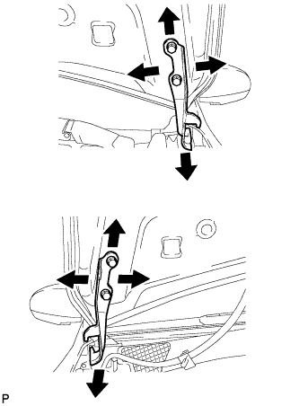
Loosen the 4 hinge bolts of the hood.
-
Adjust the clearance between the hood and front fender by moving the hood.
-
Tighten the 4 hinge bolts after the adjustment.
- Torque:
- 13 N*m { 133 kgf*cm, 10 ft.*lbf }
-
-
Adjust the height of the front end of the hood using the cushion rubbers.
-
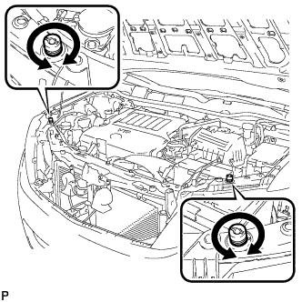
Adjust the 2 cushion rubbers so that the heights of the hood and fender are aligned.
Tech Tips
Raise or lower the front end of the hood by turning the 2 cushion rubbers.
-
-
Adjust the hood lock.
-
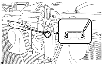
Text in Illustration *1 Protective Tape Using a screwdriver, remove the hood lock nut cap.
Tech Tips
Tape the screwdriver tip before use.
-
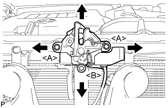
Loosen the 3 bolts.
-
Tighten the bolts after the adjustment.
- Torque:
- <A>
- 7.5 N*m { 77 kgf*cm, 66 in.*lbf }
- Torque:
- <B>
- 8.0 N*m { 82 kgf*cm, 71 in.*lbf }
-
Check that the striker can engage with the hood lock smoothly.
-
-
Install a new hood lock nut cap.
-