POWER WINDOW CONTROL SYSTEM Rear Power Window RH does not Operate with Rear Power Window Switch RH
DESCRIPTION
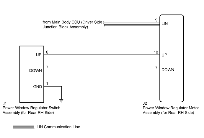
When the engine is running or the ignition switch is ON, the power window regulator motor assembly (for rear RH side) is operated by the power window regulator switch assembly (for rear RH side). The power window regulator motor assembly (for rear RH side) has motor, regulator, and ECU functions.
Tech Tips
If the pulse sensor built into the power window regulator motor (for rear RH side) malfunctions, the power window control system enters fail-safe mode. The remote up/down and auto up/down functions cannot be operated during fail-safe mode. However, the power window can be closed by holding the power window regulator switch assembly (for rear RH side) at the auto up position, and opened manually by pushing down the power window regulator switch assembly (for rear RH side).
WIRING DIAGRAM
INSPECTION PROCEDURE
Note
-
The power window control system uses a multiplex communication system (LIN communication system). Inspect the communication function by following How to Proceed with Troubleshooting Click here. Troubleshoot the power window control system after confirming that the communication system is functioning properly.
-
When the power window regulator motor assembly (for rear RH side) is reinstalled or replaced, the power window control system must be initialized.
-
After a door glass or a door glass run has been replaced, the jam protection function may operate unexpectedly when the auto up function is used. In such cases, the auto up function can be reinitialized by repeating the following operations at least 5 times:
-
Close the power window by fully pulling up the power window regulator switch assembly (for rear RH side) and holding it at the auto up position.
-
Open the power window by fully pushing down the power window regulator switch assembly (for rear RH side).
-
When the ECU determines that the power window regulator motor assembly (for rear RH side) has a malfunction, DTC B2311 is set.
PROCEDURE
-
READ VALUE USING GTS (Main Body)
-
Connect the GTS to the DLC3.
-
Turn the ignition switch to ON.
-
Turn the GTS on.
-
Enter the following menus: Body Electrical / Main Body / Data List.
-
Read the Data List according to the display on the GTS.
Main Body Tester Display Measurement Item/Range Normal Condition Diagnostic Note Communication RR-Door Motor Connection status between power window regulator motor (for rear RH) and main body ECU (driver side junction block assembly) / OK or STOP OK: Normal communication
STOP: Communication stopped
- OK On the GTS screen, OK is displayed.
NG 
GO TO LIN COMMUNICATION SYSTEM (Proceed to How to Proceed with Troubleshooting) Click here
OK 
-
-
READ VALUE USING GTS (RR-Door Motor)
-
Enter the following menus: Body Electrical / RR-Door Motor / Data List.
-
Read the Data List according to the display on the GTS.
RR-Door Motor Tester Display Measurement Item/Range Normal Condition Diagnostic Note RR Door P/W Up SW Rear RH side power window manual up switch signal / ON or OFF ON: Rear RH door power window manual up switch operated
OFF: Rear RH door power window manual up switch not operated
- RR Door P/W Down SW Rear RH side power window manual down switch signal / ON or OFF ON: Rear RH door power window manual down switch operated
OFF: Rear RH door power window manual down switch not operated
- OK On the GTS screen, ON or OFF is displayed accordingly.
NG 
INSPECT POWER WINDOW REGULATOR SWITCH ASSEMBLY (for Rear RH Side) Click here
OK
-
-
PERFORM ACTIVE TEST USING GTS (RR-Door Motor)
-
Enter the following menus: Body Electrical / RR-Door Motor / Active Test.
-
Perform the Active Test according to the display on the GTS.
RR-Door Motor Tester Display Test Part Control Range Diagnostic Note Power Window Power window OFF / UP / DOWN - OK Rear RH power window operates normally. CAUTION:
Be careful to avoid injuries as this test causes vehicle parts to move. During the Active Test, the jam protection function will not operate.
NG
REPLACE POWER WINDOW REGULATOR MOTOR ASSEMBLY (for Rear RH side) Click here
OK 
REPLACE MAIN BODY ECU (DRIVER SIDE JUNCTION BLOCK ASSEMBLY) Click here
-
-
INSPECT POWER WINDOW REGULATOR SWITCH ASSEMBLY (for Rear RH Side)
-
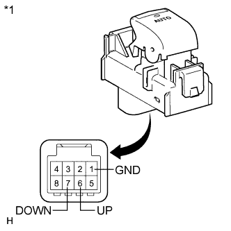
Text in Illustration *1 Component without harness connected
(Power Window Regulator Switch Assembly (for Rear RH Side))
Remove the power window regulator switch assembly (for rear RH side) Click here.
-
Measure the resistance according to the value(s) in the table below.
Standard Resistance Tester Connection Condition Specified Condition 6 (UP) - 1 (GND) Auto up or up position Below 1 Ω 7 (DOWN) - 1 (GND) Auto down or down position Below 1 Ω
NG
REPLACE POWER WINDOW REGULATOR SWITCH ASSEMBLY (for Rear RH side) Click here
OK
-
-
CHECK HARNESS AND CONNECTOR (REAR RH SIDE SWITCH - REAR RH SIDE MOTOR AND BODY GROUND)
-
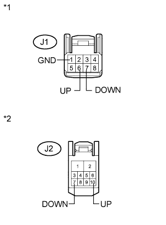
Text in Illustration *1 Front view of wire harness connector
(to Power Window Regulator Switch Assembly (for Rear RH Side))
*2 Front view of wire harness connector
(to Power Window Regulator Motor Assembly (for Rear RH Side))
Disconnect the power window regulator motor assembly (for rear RH side) connector.
-
Measure the resistance according to the value(s) in the table below.
Standard Resistance Tester Connection Condition Specified Condition J1-6 (UP) - J2-10 (UP) Always Below 1 Ω J1-7 (DOWN) - J2-7 (DOWN) Always Below 1 Ω J1-1 (GND) - Body ground Always Below 1 Ω J1-6 (UP) - Body ground Always 10 kΩ or higher J1-7 (DOWN) - Body ground Always 10 kΩ or higher J2-10 (UP) - Body ground Always 10 kΩ or higher J2-7 (DOWN) - Body ground Always 10 kΩ or higher
NG
REPAIR OR REPLACE HARNESS OR CONNECTOR
OK
REPLACE POWER WINDOW REGULATOR MOTOR ASSEMBLY (for Rear RH side) Click here
-