INSTRUMENT PANEL SAFETY PAD INSTALLATION

-
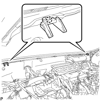
INSTALL INSTRUMENT PANEL STAY
-

Engage the 3 claws to install the 3 instrument panel stays.
-
-
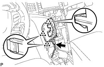
INSTALL INSTRUMENT PANEL CLIP
-
Engage the 2 claws to install the 2 instrument panel clips.
-
-
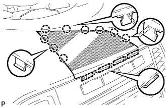
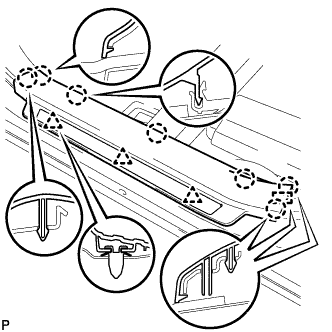
INSTALL INSTRUMENT PANEL SAFETY PAD ASSEMBLY
-
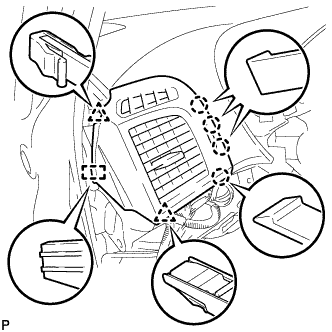
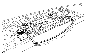
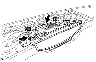
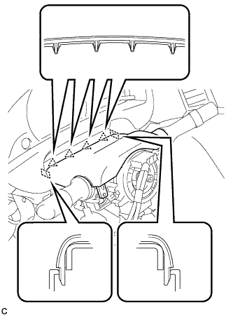
Engage the 4 claws and guide, and temporarily install the instrument panel safety pad assembly as shown in the illustration.
-
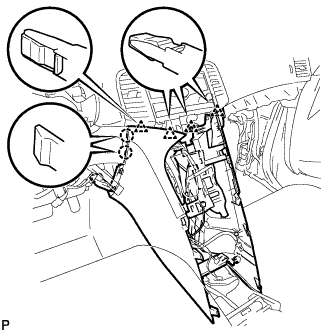
Install the 2 passenger airbag bolts <A> or <B>.
- Torque:
- 20 N*m { 204 kgf*cm, 15 ft.*lbf }
-
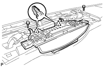
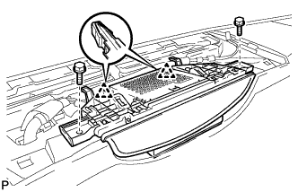
Install the instrument panel safety pad assembly with the 2 bolts <C> and nut <G> or <H>.
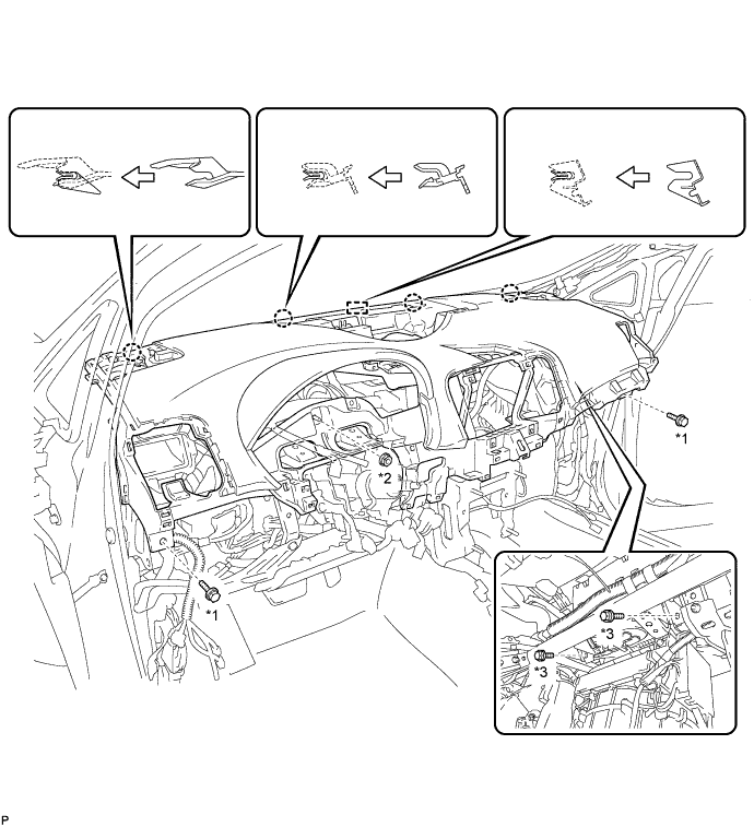
Text in Illustration *1 Bolt <C> *2 Nut <G> or <H> *3 Bolt <A> or <B> -
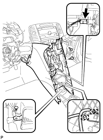
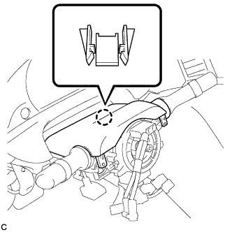
Install the bolt <D>.
- Torque:
- 8.0 N*m { 82 kgf*cm, 71 in.*lbf }
-
Connect the connectors.
-
-
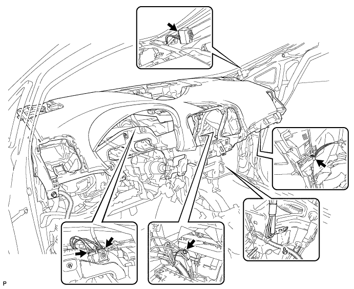
CONNECT INSTRUMENT PANEL WIRE ASSEMBLY
-
Check that the ignition switch is off.
-
Check that the cable is disconnected from the negative (-) battery terminal.
CAUTION:
Wait at least 90 seconds after disconnecting the cable from the negative (-) battery terminal to disable the SRS system.
-

Connect the 2 connectors.
Note
When connecting the airbag connector, take care not to damage the airbag wire harness.
-
-
INSTALL SHIFT LEVER ASSEMBLY
for U760E: Click here
for U760F: Click here
-
INSTALL NO. 4 INSTRUMENT PANEL REGISTER ASSEMBLY
-
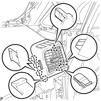
Engage the 4 claws, 2 clips and guide to install the No. 4 instrument panel register assembly.
-
-
INSTALL FRONT PILLAR GARNISH CORNER PIECE RH (for 6 Speakers)
-
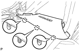
Engage the 3 claws to install the front pillar garnish corner piece RH.
-
-
INSTALL FRONT PILLAR GARNISH CORNER PIECE RH (for 13 Speakers)
-
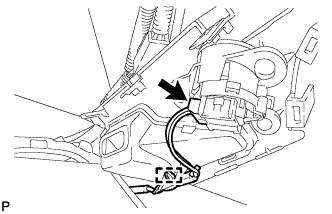
Connect the connector.
-
Engage the clamp.
-
Engage the 3 claws to install the front pillar garnish corner piece RH.
-
-
INSTALL FRONT PILLAR GARNISH RH
Tech Tips
Use the same procedure as for the LH side Click here.
-
CONNECT FRONT DOOR OPENING TRIM WEATHERSTRIP RH
-
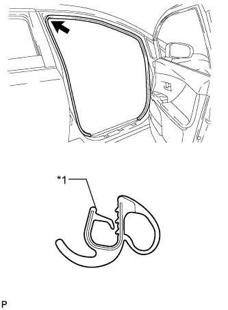
Text in Illustration *1 Alignment mark (White) Align the alignment mark (White) on the weatherstrip with the protruding portion on the body indicated by the arrow in the illustration, and install the front door opening trim weatherstrip RH.
Note
After installation, check that the corners fit correctly.
-
-
INSTALL FRONT NO. 2 SPEAKER ASSEMBLY (for RH Side)
Tech Tips
Use the same procedure as for the LH side Click here.
-
INSTALL NO. 3 INSTRUMENT PANEL SPEAKER PANEL SUB-ASSEMBLY
-

Engage the 2 guides, 6 claws and 2 clips to install the No. 3 instrument panel speaker panel sub-assembly.
-
-
INSTALL NO. 1 INSTRUMENT PANEL REGISTER ASSEMBLY
-
Engage the 4 claws, 2 clips and guide to install the No. 1 instrument panel register assembly.
-
-
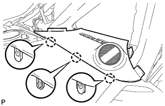
INSTALL FRONT PILLAR GARNISH CORNER PIECE LH (for 6 Speakers)
-
Engage the 3 claws to install the front pillar garnish corner piece LH.
-
-
INSTALL FRONT PILLAR GARNISH CORNER PIECE LH (for 13 Speakers)
-
Connect the connector.
-
Engage the clamp.
-
Engage the 3 claws to install the front pillar garnish corner piece LH.
-
-
INSTALL FRONT PILLAR GARNISH LH
-
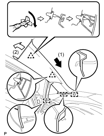
Engage the 3 guides.
-
Turn the end of the front pillar garnish clip 90° with needle-nosed pliers and install it to the front pillar garnish RH.
Tech Tips
Tape the needle-nosed pliers tip before use.
-
Engage the 2 clips to install the front pillar garnish LH.
-
-
CONNECT FRONT DOOR OPENING TRIM WEATHERSTRIP LH
-
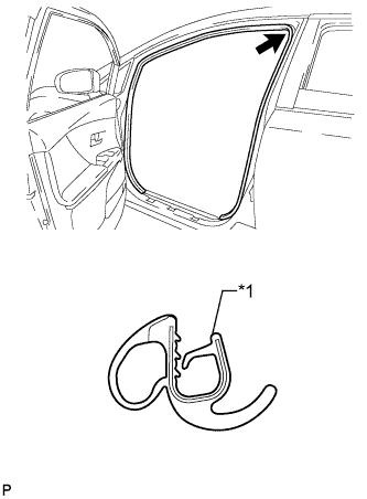
Text in Illustration *1 Alignment mark (Yellow) Align the alignment mark (Yellow) on the weatherstrip with the protruding portion on the body indicated by the arrow in the illustration, and install the front door opening trim weatherstrip LH.
Note
After installation, check that the corners fit correctly.
-
-
INSTALL FRONT NO. 2 SPEAKER ASSEMBLY (for LH Side)
-
Connect the connector.
-
Install the front No. 2 speaker assembly with the 2 bolts.
- Torque:
- 11 N*m { 112 kgf*cm, 8 ft.*lbf }
-
-
INSTALL NO. 1 INSTRUMENT PANEL SPEAKER PANEL SUB-ASSEMBLY
-

Engage the 2 guides, 6 claws and 2 clips to install the No. 1 instrument panel speaker panel sub-assembly.
-
-
INSTALL LOWER INSTRUMENT PANEL FINISH PANEL (w/o Smart Entry and Start System)
-
Engage the 4 claws to install the lower instrument panel finish panel.
-
-
INSTALL LOWER INSTRUMENT PANEL FINISH PANEL (w/ Smart Entry and Start System)
-
Connect the connector.
-
Engage the 4 claws to install the lower instrument panel finish panel.
-
-
INSTALL RADIO AND DISPLAY RECEIVER ASSEMBLY WITH BRACKET (for Radio and Display Type)
-
Connect each connector.
-
Engage the 2 clips.
-
Install the radio and display receiver assembly with bracket with the 4 bolts.
- Torque:
- 11 N*m { 112 kgf*cm, 8 ft.*lbf }
-
-
INSTALL NAVIGATION RECEIVER ASSEMBLY WITH BRACKET (for Navigation Receiver Type)
-
Connect each connector.
-
Engage the 2 clips.
-
Install the navigation receiver assembly with bracket with the 4 bolts.
- Torque:
- 11 N*m { 112 kgf*cm, 8 ft.*lbf }
-
-
INSTALL FRONT NO. 4 SPEAKER ASSEMBLY (for 13 Speakers)
-
Connect the connector.
-
Install the center speaker assembly with the 2 bolts.
- Torque:
- 11 N*m { 112 kgf*cm, 8 ft.*lbf }
-
-
INSTALL NO. 2 INSTRUMENT PANEL SPEAKER PANEL SUB-ASSEMBLY
-
Engage the 4 guides and 9 claws to install the No. 2 instrument panel speaker panel sub-assembly.
-
-
INSTALL CONSOLE BOX SUB-ASSEMBLY
-
Engage the 2 claws and 4 clips.
-
Engage the 2 clamps.
-
Connect the connector.
-
Install the clip.
-
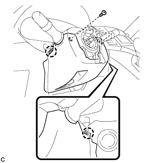
Install the console box sub-assembly with the 2 screws <E> or <F>.
-
-
INSTALL POSITION INDICATOR HOUSING ASSEMBLY
-
Engage the 3 clips to position indicator housing assembly.
-
Connect the connector.
-
Move the shift lever to P.
-
-
INSTALL SHIFT LEVER KNOB SUB-ASSEMBLY
-
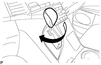
Turn the shift lever knob clockwise to install the shift lever knob sub-assembly.
-
-
INSTALL LOWER INSTRUMENT PANEL SUB-ASSEMBLY
-
Connect the connectors.
-
Engage the 5 guides, 2 clips and claw.
-
Install the lower instrument panel sub-assembly with the bolt <C> and 4 screws <E> or <F>.
-
-
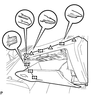
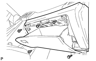
INSTALL NO. 2 INSTRUMENT PANEL UNDER COVER SUB-ASSEMBLY
-
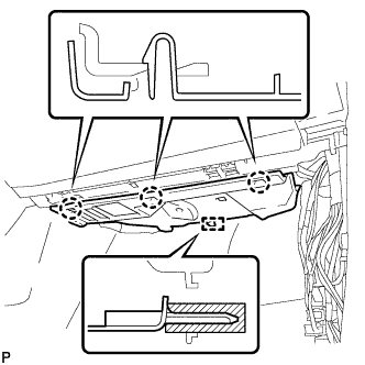
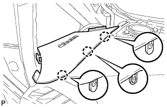
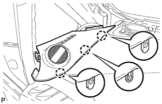
Engage the guide and 3 claws to install the No. 2 instrument panel under cover sub-assembly.
-
-
INSTALL COWL SIDE TRIM SUB-ASSEMBLY RH
Tech Tips
Use the same procedure as for the LH side Click here.
-
INSTALL FRONT DOOR SCUFF PLATE RH
Tech Tips
Use the same procedure as for the LH side Click here.
-
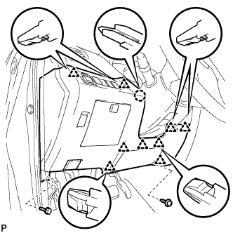
INSTALL LOWER NO. 1 INSTRUMENT PANEL FINISH PANEL
-
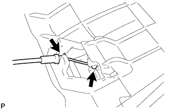
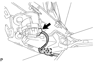
Connect the hood lock control cable.
-
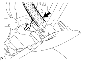
Connect the aspirator duct and connector.
-
Connect the connectors.
-
Engage the claw and 9 clips.
-
Install the lower No. 1 instrument panel finish panel with the bolt <C> and screw <E> or <F>.
-
-
INSTALL COWL SIDE TRIM SUB-ASSEMBLY LH
-
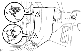
Engage the 2 clips to install the cowl side trim sub-assembly LH.
-
Install the clip.
-
-
INSTALL FRONT DOOR SCUFF PLATE LH
-
Engage the guide, 3 clips and the 7 claws to install the front door scuff plate LH.
-
-
INSTALL AIR CONDITIONING CONTROL ASSEMBLY
-
Connect the connector.
-
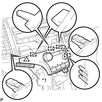
Engage the 2 clips and 4 guides.
-
Remove the protective tape.
Text in Illustration *1 Protective Tape -
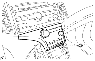
Install the air conditioning control assembly with the screw.
-
-
INSTALL CONSOLE BOX ASSEMBLY
-
Connect the connectors.
-
Engage the 2 claws.
-
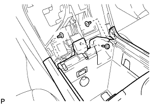
Install the screw and 2 clips.
-
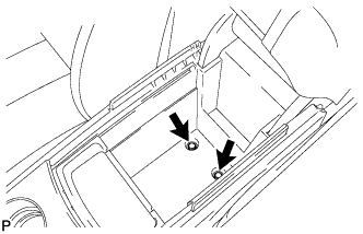
Install the console box assembly with the 2 bolts.
-
-
INSTALL NO. 2 CONSOLE BOX CARPET
-
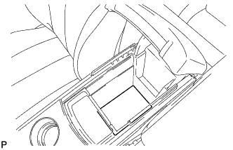
Install the No. 2 console box carpet.
-
-
INSTALL UPPER CONSOLE PANEL SUB-ASSEMBLY
-
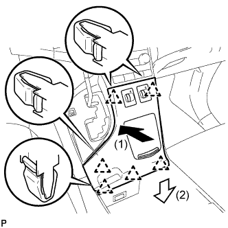
Connect the connectors.
-
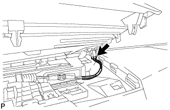
Engage the 6 clips to install the upper console panel sub-assembly as shown in the illustration.
-
-
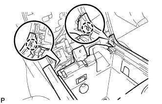
INSTALL ACCESSORY METER ASSEMBLY (w/o Rear View Monitor System)
-
Connect the connector.
-
Engage the 2 clamps.
-
Engage the 2 clips.
-
Install the accessory meter assembly with the 2 bolts.
-
-
INSTALL ACCESSORY METER ASSEMBLY (w/ Rear View Monitor System)
-
Connect the connectors.
-
Engage the 2 clamps.
-
Engage the 2 clips.
-
Install the accessory meter assembly with the 2 bolts.
-
-
INSTALL DEFROSTER NOZZLE GARNISH
-
Connect the connector.
-

Engage the 6 guides, 6 claws and 4 clips to install the defroster nozzle garnish as shown in the illustration.
-
-
INSTALL COMBINATION METER ASSEMBLY
-
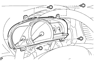
Connect the connectors.
-
Install the combination meter assembly with the 4 screws.
-
-
INSTALL INSTRUMENT CLUSTER FINISH PANEL
-
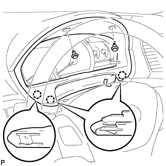
Engage the 3 claws.
-
Install the instrument cluster finish panel with the 2 clips.
-
-
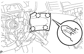
INSTALL TURN SIGNAL SWITCH ASSEMBLY WITH SPIRAL CABLE SUB-ASSEMBLY
-
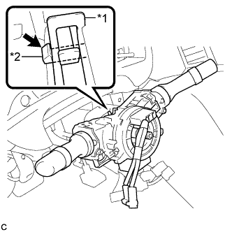
Text in Illustration *1 Clamp *2 Claw Using pliers, expand the clamp.
-
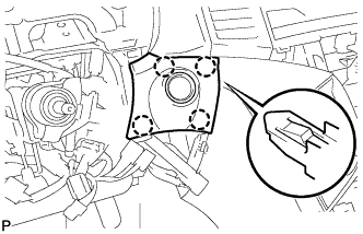
While holding the clamp expanded, install the turn signal switch assembly with spiral cable sub-assembly to the steering column assembly and engage the claw.
-
Return the clamp to its original position.
-
Connect the connectors to the turn signal switch assembly with spiral cable sub-assembly.
-
-
INSTALL UPPER STEERING COLUMN COVER
-
Engage the 4 clips and 2 guides to install the upper steering column cover onto the instrument panel cluster finish panel.
-
Engage the claw to install the upper steering column cover.
-
-
INSTALL LOWER STEERING COLUMN COVER
-
Engage the 2 claws to install the lower steering column cover.
-
Install the 2 screws.
- Torque:
- 2.0 N*m { 20 kgf*cm, 18 in.*lbf }
-
-
ALIGN FRONT WHEELS FACING STRAIGHT AHEAD
-
ADJUST SPIRAL CABLE
-
Check that the ignition switch is off.
-
Check that the cable is disconnected from the negative (-) battery terminal.
CAUTION:
Wait at least 90 seconds after disconnecting the cable from the negative (-) battery terminal to disable the SRS system.
-
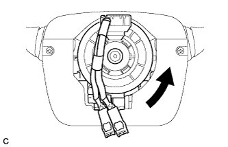
Rotate the spiral cable counterclockwise slowly by hand until it stops.
Note
Do not turn the spiral cable using the airbag wire harness.
-
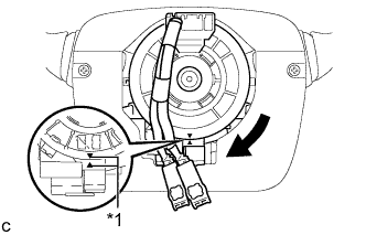
Text in Illustration *1 Alignment Mark Rotate the spiral cable clockwise approximately 2.5 turns to align the alignment marks.
Note
Do not turn the spiral cable using the airbag wire harness.
Tech Tips
The spiral cable will rotate approximately 2.5 turns to both the left and right from the center.
-
-
INSTALL STEERING WHEEL ASSEMBLY
-
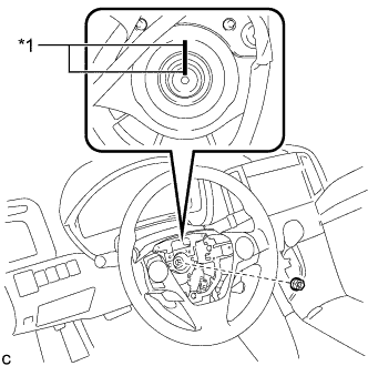
Text in Illustration *1 Matchmark Install the steering wheel assembly aligning the matchmarks on the steering wheel assembly and steering main shaft.
-
Install the steering wheel assembly set nut.
- Torque:
- 50 N*m { 510 kgf*cm, 37 ft.*lbf }
-
Connect each connector to the spiral cable sub-assembly.
-
-
INSTALL STEERING PAD
-
INSPECT STEERING WHEEL CENTER POINT
-
CONNECT CABLE TO NEGATIVE BATTERY TERMINAL
Note
When disconnecting the cable, some systems need to be initialized after the cable is reconnected Click here.
-
INSPECT STEERING PAD
-
Make sure that the horn sounds.
Tech Tips
If the horn does not sound, inspect the horn system Click here.
-
-
INSPECT SHIFT LEVER POSITION
for U760E: Click here
for U760F: Click here
-
ADJUST SHIFT LEVER POSITION
for U760E: Click here
for U760F: Click here
-
INSPECT SRS WARNING LIGHT
-
Inspect the SRS warning light Click here.
-