INSTRUMENT PANEL SAFETY PAD REMOVAL

-
PRECAUTION
-
ALIGN FRONT WHEELS FACING STRAIGHT AHEAD
-
DISCONNECT CABLE FROM NEGATIVE BATTERY TERMINAL
CAUTION:
Wait at least 90 seconds after disconnecting the cable from the negative (-) battery terminal to disable the SRS system.
Note
When disconnecting the cable, some systems need to be initialized after the cable is reconnected Click here.
-
REMOVE STEERING PAD
-
REMOVE STEERING WHEEL ASSEMBLY
-
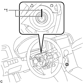
Text in Illustration *1 Matchmark Remove the steering wheel assembly set nut.
-
Put matchmarks on the steering wheel assembly and the steering main shaft.
-
Disconnect each connector from the spiral cable sub-assembly.
-
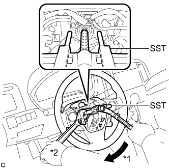
Text in Illustration *1 Turn *2 Hold Using SST, remove the steering wheel assembly.
- SST
- 09950-50013 ( 09951-05010, 09952-05010, 09953-05020, 09954-05070 )
Note
-
Apply a small amount of grease to the threads and tip of SST (09953-05020) before use.
-
Do not rotate the spiral cable with the battery connected and the ignition switch ON.
-
Ensure that the steering wheel is installed and aligned straight when inspecting the steering sensor.
-
-
REMOVE LOWER STEERING COLUMN COVER
-
Remove the 2 screws.
-
Push the right and left sides of the lower steering column cover, and disengage the 2 claws to remove the lower steering column cover.
-
-
REMOVE UPPER STEERING COLUMN COVER
-
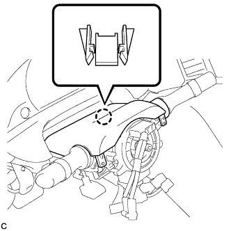
Disengage the claw.
-
Disengage the 4 clips and 2 guides to remove the upper steering column cover.
-
-
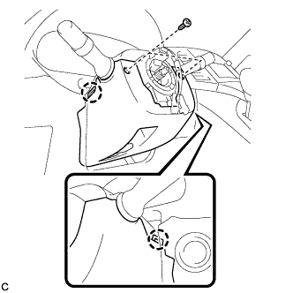
REMOVE TURN SIGNAL SWITCH ASSEMBLY WITH SPIRAL CABLE SUB-ASSEMBLY
-
Disconnect the connectors from the turn signal switch assembly with spiral cable sub-assembly.
-
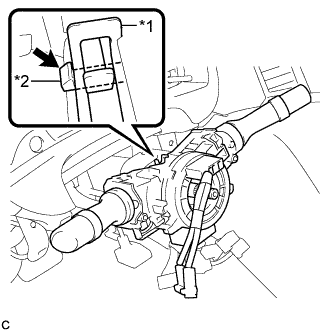
Text in Illustration *1 Clamp *2 Claw Using pliers, expand the clamp.
-
While holding the clamp expanded, raise the claw using a screwdriver to disengage it, and then remove the turn signal switch assembly with spiral cable sub-assembly from the steering column assembly.
Note
-
Do not replace the spiral cable with the battery connected and the ignition switch on.
-
Do not rotate the spiral cable without the steering wheel with the battery connected and the ignition switch on.
-
Ensure that the steering wheel is installed and aligned straight when inspecting the steering sensor.
-
Do not remove the steering sensor from the spiral cable.
-
-
-
REMOVE INSTRUMENT CLUSTER FINISH PANEL
-
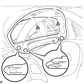
Remove the 2 clips.
-
Disengage the 3 claws and remove the instrument cluster finish panel.
-
-
REMOVE COMBINATION METER ASSEMBLY
-
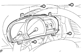
Remove the 4 screws.
-
Disconnect the connectors and remove the combination meter assembly.
-
-
REMOVE DEFROSTER NOZZLE GARNISH
-
Pull the defroster nozzle garnish in the direction indicated by the arrow to disengage the 4 clips, 6 claws and 6 guides.
-
Disconnect the connector and remove the defroster nozzle garnish.
-
-
REMOVE ACCESSORY METER ASSEMBLY (w/o Rear View Monitor System)
-
Remove the 2 bolts.
-
Disengage the 2 clips.
-
Disengage the 2 clamps.
-
Disconnect the connector and remove the accessory meter assembly.
-
-
REMOVE ACCESSORY METER ASSEMBLY (w/ Rear View Monitor System)
-
Remove the 2 bolts.
-
Disengage the 2 clips.
-
Disengage the 2 clamps.
-
Disconnect the connectors and remove the accessory meter assembly.
-
-
REMOVE UPPER CONSOLE PANEL SUB-ASSEMBLY
-
Pull the upper console panel sub-assembly in the direction indicated by the arrow to disengage the 6 clips.
-
Disconnect the connectors and remove the upper console panel sub-assembly.
-
-
REMOVE NO. 2 CONSOLE BOX CARPET
-
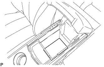
Remove the No. 2 console box carpet.
-
-
REMOVE CONSOLE BOX ASSEMBLY
-
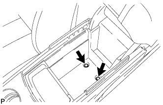
Remove the 2 bolts.
-
Remove the screw and 2 clips.
-
Disengage the 2 claws.
-
Disconnect the connectors and remove the console box assembly.
-
-
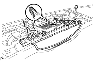
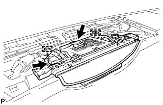
REMOVE AIR CONDITIONING CONTROL ASSEMBLY
-
Remove the screw.
-
Text in Illustration *1 Protective Tape Apply protective tape to the area shown in the illustration.
-
Using a moulding remover, disengage the 2 clips and 4 guides as shown in the illustration.
-
Disconnect the connector and remove the air conditioning control assembly.
-
-
REMOVE FRONT DOOR SCUFF PLATE LH
-
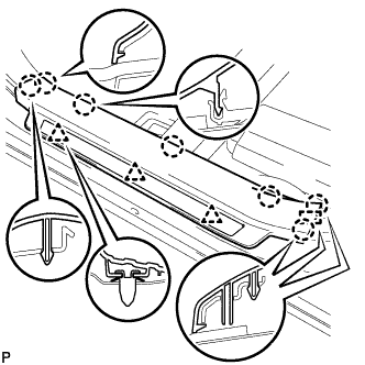
Disengage the 3 clips, 7 claws and guide, and remove the front door scuff plate LH.
-
-
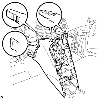
REMOVE COWL SIDE TRIM SUB-ASSEMBLY LH
-
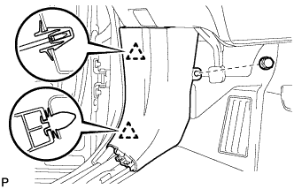
Remove the clip.
-
Disengage the 2 clips and remove the cowl side trim sub-assembly LH.
-
-
REMOVE LOWER NO. 1 INSTRUMENT PANEL FINISH PANEL
-
Remove the bolt <C> and screw <E> or <F>.
-
Disengage the claw and 9 clips.
-
Disconnect the connectors.
-
Disconnect the connector and aspirator duct.
-
Disconnect the hood lock control cable and remove the lower No. 1 instrument panel finish panel.
-
-
REMOVE FRONT DOOR SCUFF PLATE RH
Tech Tips
Use the same procedure as for the LH side Click here.
-
REMOVE COWL SIDE TRIM SUB-ASSEMBLY RH
Tech Tips
Use the same procedure as for the LH side Click here.
-
REMOVE NO. 2 INSTRUMENT PANEL UNDER COVER SUB-ASSEMBLY
-
Push the 3 claws in the direction indicated by the arrow to disengage them.
-
Disengage the guide and remove the No. 2 instrument panel under cover sub-assembly.
-
-
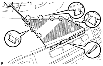
REMOVE LOWER INSTRUMENT PANEL SUB-ASSEMBLY
-
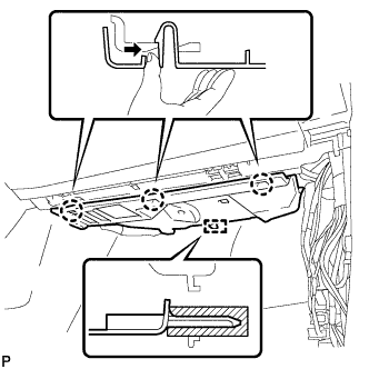
Remove the bolt <C> and 4 screws <E> or <F>.
-
Disengage the claw, 3 clips and 5 guides.
-
Disconnect the connectors and remove the lower instrument panel sub-assembly.
-
-
REMOVE SHIFT LEVER KNOB SUB-ASSEMBLY
-
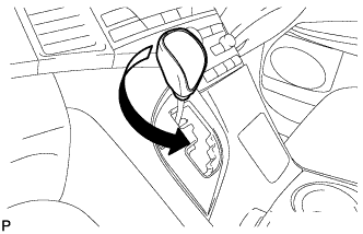
Turn the shift lever knob counterclockwise and remove the shift lever knob sub-assembly.
-
-
REMOVE POSITION INDICATOR HOUSING ASSEMBLY
-
Move the shift lever to N.
-
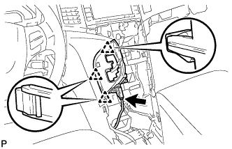
Disconnect the connector.
-
Disengage the 3 clips and remove the position indicator housing assembly.
-
-
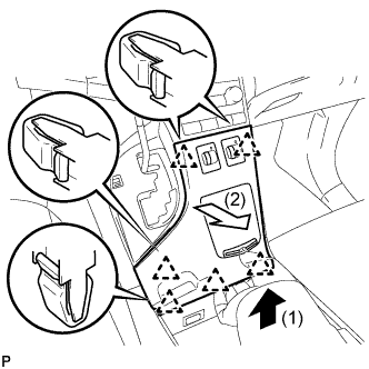
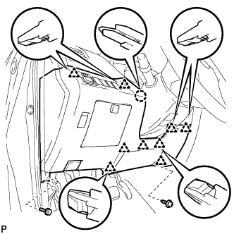
REMOVE CONSOLE BOX SUB-ASSEMBLY
-
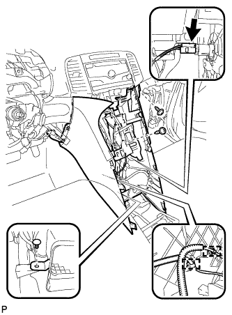
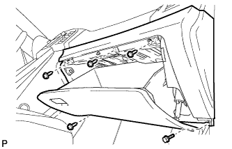
Remove the 2 screws <E> or <F>.
-
Using a clip remover, remove the clip.
-
Disconnect the connector.
-
Disengage the 2 clamps.
-
Disengage the 2 claws and 4 clips and remove the console box sub-assembly.
-
-
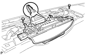
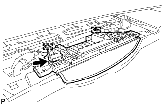
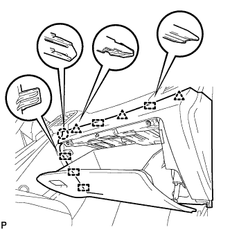
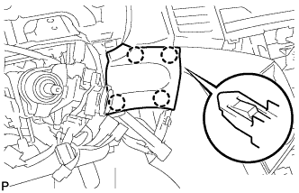
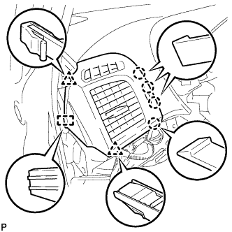
REMOVE NO. 2 INSTRUMENT PANEL SPEAKER PANEL SUB-ASSEMBLY
-
Text in Illustration *1 Protective Tape Using a screwdriver, disengage the 9 claws and 4 guides, and remove the No. 2 instrument panel speaker panel sub-assembly.
Tech Tips
Tape the screwdriver tip before use.
-
-
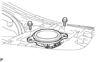
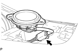
REMOVE FRONT NO. 4 SPEAKER ASSEMBLY (for 13 Speakers)
-
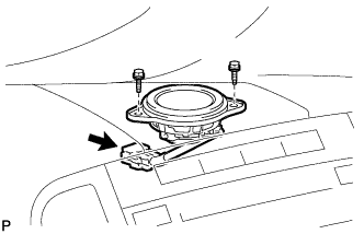
Remove the 2 bolts.
-
Disconnect the connector and remove the center speaker assembly.
-
-
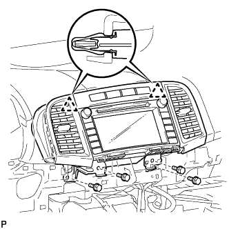
REMOVE RADIO AND DISPLAY RECEIVER ASSEMBLY WITH BRACKET (for Radio and Display Type)
-
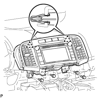
Remove the 4 bolts.
-
Disengage the 2 clips.
-
Disconnect each connector and remove the radio and display receiver assembly with bracket.
-
-
REMOVE NAVIGATION RECEIVER ASSEMBLY WITH BRACKET (for Navigation Receiver Type)
-
Remove the 4 bolts.
-
Disengage the 2 clips.
-
Disconnect each connector and remove the navigation receiver assembly with bracket.
-
-
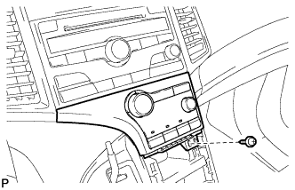
REMOVE LOWER INSTRUMENT PANEL FINISH PANEL (w/o Smart Entry and Start System)
-
Disengage the 4 claws and remove the lower instrument panel finish panel.
-
-
REMOVE LOWER INSTRUMENT PANEL FINISH PANEL (w/ Smart Entry and Start System)
-
Disengage the 4 claws.
-
Disconnect the connector and remove the lower instrument panel finish panel.
-
-
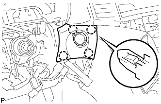
REMOVE NO. 1 INSTRUMENT PANEL SPEAKER PANEL SUB-ASSEMBLY
-
Text in Illustration *1 Protective Tape Using a screwdriver, disengage the 2 clips, 6 claws and 2 guides, and remove the No. 1 instrument panel speaker panel sub-assembly.
Tech Tips
Tape the screwdriver tip before use.
-
-
REMOVE FRONT NO. 2 SPEAKER ASSEMBLY (for LH Side)
-
Remove the 2 bolts.
-
Disconnect the connector and remove the front No. 2 speaker assembly.
-
-
DISCONNECT FRONT DOOR OPENING TRIM WEATHERSTRIP LH
-
REMOVE FRONT PILLAR GARNISH LH
-
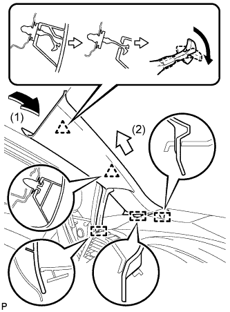
Pull the upper part of the garnish toward the inside of the cabin and disengage the 2 clips.
Tech Tips
Make the front pillar garnish LH hang down from the front pillar garnish clip.
-
Turn the end of the front pillar garnish clip 90° with needle-nosed pliers and remove it from the front pillar garnish LH.
Note
-
Front pillar garnish clips are reusable if they are not removed from the vehicle and have no damage.
-
Replace the front pillar garnish clips with new ones if they are removed from the vehicle.
Tech Tips
Tape the needle-nosed pliers tip before use.
-
-
Disengage the 3 guides and remove the front pillar garnish LH.
-
-
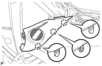
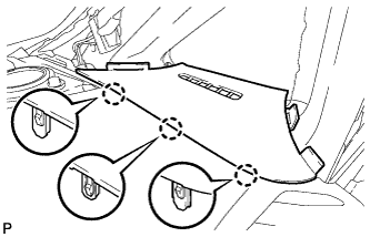
REMOVE FRONT PILLAR GARNISH CORNER PIECE LH (for 6 Speakers)
-
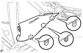
Disengage the 3 claws and remove the front pillar garnish corner piece LH.
-
-
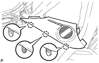
REMOVE FRONT PILLAR GARNISH CORNER PIECE LH (for 13 Speakers)
-
Disengage the 3 claws.
-
Disengage the clamp.
-
Disconnect the connector and remove the front pillar garnish corner piece LH.
-
-
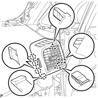
REMOVE NO. 1 INSTRUMENT PANEL REGISTER ASSEMBLY
-
Disengage the 4 claws, 2 clips and guide, and remove the No. 1 instrument panel register assembly.
-
-
REMOVE NO. 3 INSTRUMENT PANEL SPEAKER PANEL SUB-ASSEMBLY
-
Text in Illustration *1 Protective Tape Using a screwdriver, disengage the 2 clips, 6 claws and 2 guides, and remove the No. 3 instrument panel speaker panel sub-assembly.
Tech Tips
Tape the screwdriver tip before use.
-
-
REMOVE FRONT NO. 2 SPEAKER ASSEMBLY (for RH Side)
Tech Tips
Use the same procedure as for the LH side Click here.
-
DISCONNECT FRONT DOOR OPENING TRIM WEATHERSTRIP RH
-
REMOVE FRONT PILLAR GARNISH RH
Tech Tips
Use the same procedure as for the LH side Click here.
-
REMOVE FRONT PILLAR GARNISH CORNER PIECE RH (for 6 Speakers)
-
Disengage the 3 claws and remove the front pillar garnish corner piece RH.
-
-
REMOVE FRONT PILLAR GARNISH CORNER PIECE RH (for 13 Speakers)
-
Disengage the 3 claws.
-
Disengage the clamp.
-
Disconnect the connector and remove the front pillar garnish corner piece RH.
-
-
REMOVE NO. 4 INSTRUMENT PANEL REGISTER ASSEMBLY
-
Disengage the 4 claws, 2 clips and guide, and remove the No. 4 instrument panel register assembly.
-
-
REMOVE SHIFT LEVER ASSEMBLY
for U760E: Click here
for U760F: Click here
-
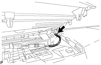
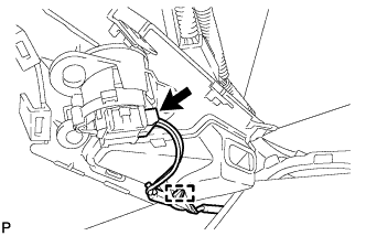
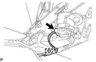
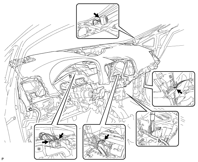
DISCONNECT INSTRUMENT PANEL WIRE ASSEMBLY
-
Check that the ignition switch is off.
-
Check that the cable is disconnected from the negative (-) battery terminal.
CAUTION:
Wait at least 90 seconds after disconnecting the cable from the negative (-) battery terminal to disable the SRS system.
-
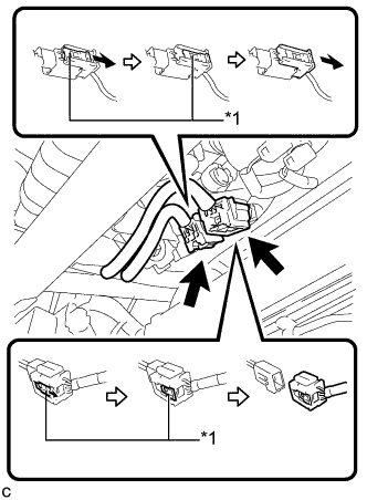
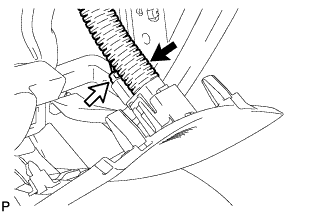
Text in Illustration *1 Slider Slide the 2 sliders to release the 2 locks, and then disconnect the 2 connectors.
Note
When disconnecting the airbag connector, take care not to damage the airbag wire harness.
-
-
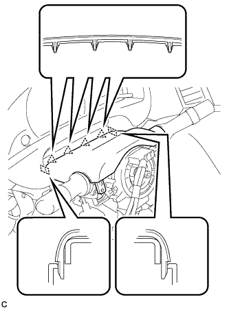
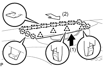
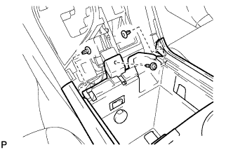
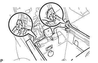
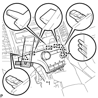
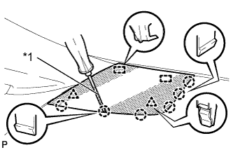
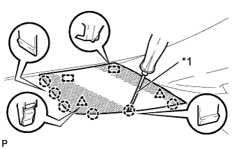
REMOVE INSTRUMENT PANEL SAFETY PAD ASSEMBLY
-
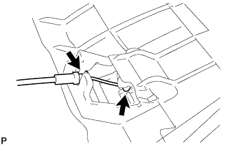
Remove the bolt <D>.
-
Disconnect the connectors.
-
Remove the 2 bolts <C> and nut <G> or <H>.
-
Remove the 2 passenger airbag bolts <A> or <B>.
-
Disengage the 4 claws and guide, and remove the instrument panel safety pad assembly as shown in the illustration.
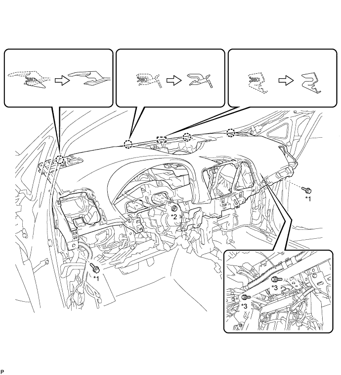
Text in Illustration *1 Bolt <C> *2 Nut <G> or <H> *3 Bolt <A> or <B>
-
-
REMOVE INSTRUMENT PANEL CLIP
-
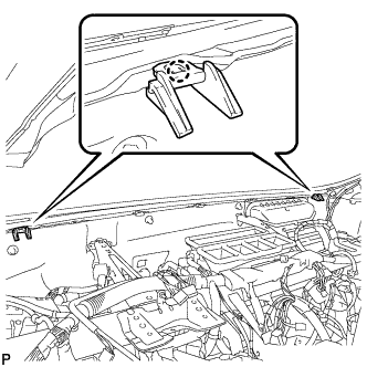
Disengage the 2 claws and remove the 2 instrument panel clips.
-
-
REMOVE INSTRUMENT PANEL STAY
-

Disengage the 3 claws and remove the 3 instrument panel stays.
-