AIR CONDITIONING UNIT REMOVAL

Note
Make sure to select FACE mode before disconnecting the cable from the negative (-) battery terminal.
-
RECOVER REFRIGERANT FROM REFRIGERATION SYSTEM
-
Start up the engine.
-
Turn the A/C switch on.
-
Operate the cooler compressor at an engine speed of approximately 1000 rpm for 5 to 6 minutes to circulate the refrigerant. This causes most of the compressor oil from the various components of the A/C system to collect in the A/C compressor.
-
Stop the engine.
-
Recover the refrigerant from the A/C system using a refrigerant recovery unit.
-
-
REMOVE WINDSHIELD WIPER MOTOR AND LINK ASSEMBLY
-
REMOVE OUTER COWL TOP PANEL
-
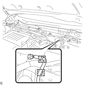
Disengage the 2 clamps and separate the wiper wire harness from the outer cowl top panel sub-assembly.
-
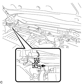
Disengage the 2 clamps and connector, and separate the wire harness from the outer cowl top panel sub-assembly (w/ Windshield Deicer).
-
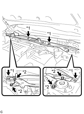
Text in Illustration *1 Bolt *2 Nut Remove the 4 bolts, 4 nuts and outer cowl top panel sub-assembly.
-
-
DISCONNECT OUTLET HEATER WATER HOSE
-
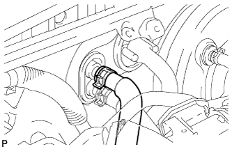
Using pliers, grip the claws of the clip and slide the clip to disconnect the outlet heater water hose.
Note
-
Do not apply excessive force to the outlet heater water hose.
-
Prepare a drain pan or cloth in case the coolant leaks.
-
-
-
DISCONNECT INLET HEATER WATER HOSE
-
Using pliers, grip the claws of the clip and slide the clip to disconnect the inlet heater water hose.
Note
-
Do not apply excessive force to the inlet heater water hose.
-
Prepare a drain pan or cloth in case the coolant leaks.
-
-
-
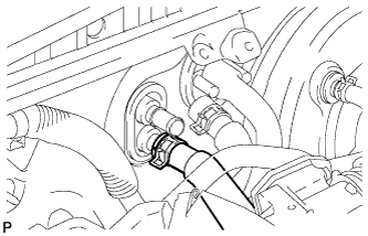
DISCONNECT SUCTION HOSE SUB-ASSEMBLY
-
Remove the bolt, and slide the hook connector.
-
Disconnect the suction hose sub-assembly.
-
Remove the O-ring from the suction hose sub-assembly.
Note
Seal the openings of the disconnected parts using vinyl tape to prevent entry of moisture and foreign matter.
-
-
DISCONNECT AIR CONDITIONING TUBE AND ACCESSORY ASSEMBLY
-
Disconnect the air conditioning tube and accessory assembly.
-
Remove the O-ring from the air conditioning tube and accessory assembly.
Note
Seal the openings of the disconnected parts using vinyl tape to prevent entry of moisture and foreign matter.
-
-
REMOVE FRONT SEAT ASSEMBLY LH
-
REMOVE FRONT SEAT ASSEMBLY RH
Tech Tips
Use the same procedure as for the LH side.
-
REMOVE INSTRUMENT PANEL SAFETY PAD ASSEMBLY
-
REMOVE STEERING POST ASSEMBLY
-
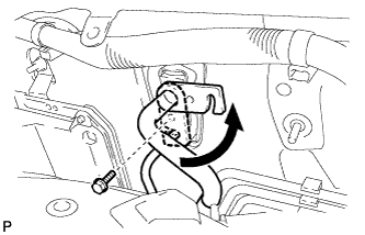
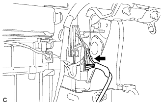
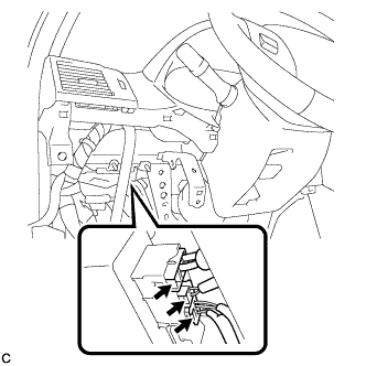
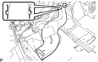
REMOVE TURN SIGNAL FLASHER ASSEMBLY
-
Disconnect the connector.
-
Disengage the clamp and remove the turn signal flasher assembly.
-
-
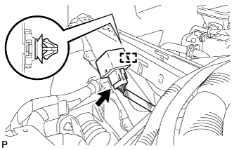
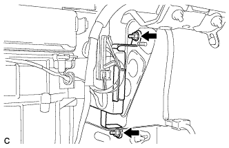
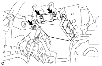
REMOVE POWER MANAGEMENT CONTROL ECU
-
Disconnect the 2 connectors.
-
Remove the 2 nuts and the power management control ECU.
-
-
REMOVE 4WD CONTROL ECU (for 4WD)
-
Disconnect the connector.
-
Remove the 2 nuts and ECU.
-
-
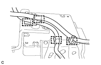
REMOVE MAIN BODY ECU (DRIVER SIDE JUNCTION BLOCK ASSEMBLY)
-
Separate the wire harness clamp from the driver side junction block assembly.
-
Disconnect the connectors from the driver side junction block assembly.
-
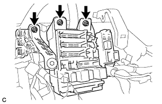
Remove the 3 nuts.
-
Disconnect the connectors from the back of the driver side junction block assembly.
-
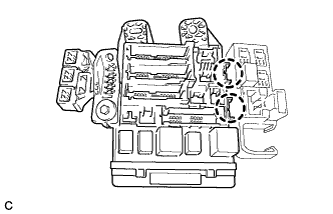
Disengage the 2 claws to remove the driver side junction block assembly.
-
-
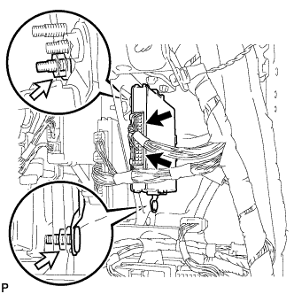
REMOVE POWER STEERING ECU ASSEMBLY
-
Disconnect the 3 connectors from the power steering ECU assembly.
-
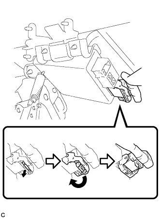
Disconnect the connector from the power steering ECU assembly.
Tech Tips
Pull out the lock of the lock lever, disengage the claw, and raise the lock lever to disconnect the connector as shown in the illustration.
-
Remove the 3 nuts and power steering ECU assembly.
-
Disengage the 4 wire harness clamps from the power steering ECU assembly
-
-
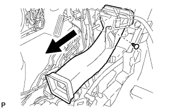
REMOVE REAR NO. 2 AIR DUCT
-
Turn back the floor carpet.
-
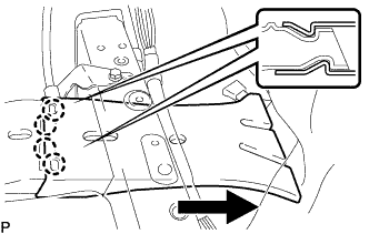
Disengage the 4 claws and remove the rear No. 2 air duct as shown in the illustration.
-
-
REMOVE REAR NO. 1 AIR DUCT
-
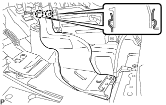
Disengage the 2 claws and remove the rear No. 1 air duct.
-
-
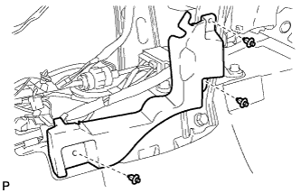
REMOVE FLOOR CARPET BRACKET LH
-
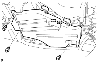
Disengage the 2 clamps.
-
Remove the 3 clips and floor carpet bracket LH.
-
-
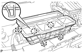
REMOVE REAR NO. 4 AIR DUCT
-
Turn back the floor carpet.
-
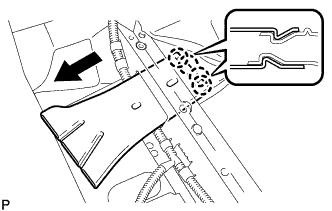
Disengage the 4 claws and remove the rear No. 4 air duct as shown in the illustration.
-
-
REMOVE REAR NO. 3 AIR DUCT
-
Disengage the 2 claws and remove the rear No. 3 air duct.
-
-
REMOVE FLOOR CARPET BRACKET RH
-
Remove the 3 clips and floor carpet bracket RH.
-
-
REMOVE NO. 1 CONSOLE BOX DUCT
-
Remove the clip and No. 1 console box duct as shown in the illustration.
-
-
REMOVE NO. 6 HEATER TO REGISTER DUCT ASSEMBLY
-
Disengage the clamp.
-
Disengage the 4 claws and remove the No. 6 heater to register duct assembly.
-
-
REMOVE NO. 3 INSTRUMENT PANEL REINFORCEMENT
-
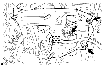
Text in Illustration *1 Bolt *2 Nut *3 Earth Wire Disengage the clamp.
-
Remove the bolt and disconnect the earth wire.
-
Remove the 2 nuts and No. 3 instrument panel reinforcement.
-
-
REMOVE NO. 1 INSTRUMENT PANEL BRACE SUB-ASSEMBLY
-
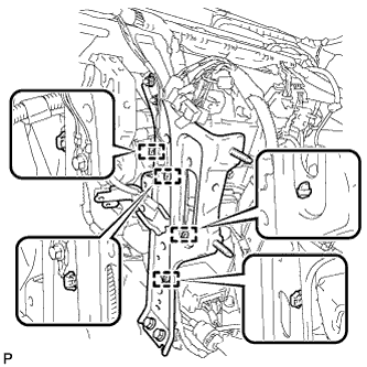
Disengage each clamp.
-
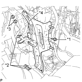
Text in Illustration *1 Screw *2 Bolt *3 Nut *4 Earth Wire Remove the screw.
-
Remove the bolt and disconnect the earth wire.
-
Remove the 2 bolts, 2 nuts and No. 1 instrument panel brace sub-assembly.
-
-
REMOVE NO. 2 INSTRUMENT PANEL BRACE SUB-ASSEMBLY
-
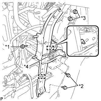
Text in Illustration *1 Screw *2 Bolt *3 Nut *4 Earth Wire Disengage each clamp.
-
Remove the screw.
-
Remove the bolt and disconnect the earth wire.
-
Remove the bolt, 2 nuts and No. 2 instrument panel brace sub-assembly.
-
-
REMOVE INSTRUMENT PANEL REINFORCEMENT ASSEMBLY WITH AIR CONDITIONING UNIT ASSEMBLY
-
Remove the bolt, 2 nuts and screw.
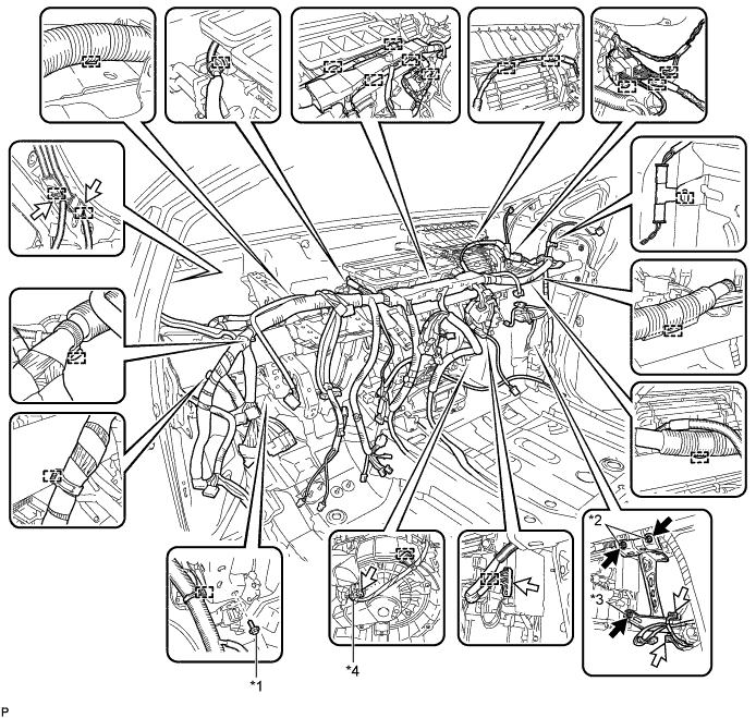
Text in Illustration *1 Bolt *2 Nut *3 Screw *4 Blower Motor Connector -
Disconnect the blower motor connector.
-
Disconnect each connector.
-
Disengage each clamp.
-
Remove the 2 bolts from the engine compartment side.
Text in Illustration *1 Bolt *2 Nut *3 Cooler Drain Hose - - -
Remove the nut.
-
Disconnect the cooler drain hose.
-
for LH side:
-
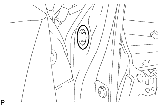
Remove the hole plug.
-
-
for RH side:
-
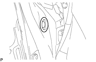
Remove the hole plug.
-
-
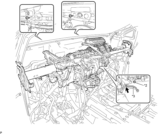
Using a T40 "TORX" socket wrench, remove the 4 "TORX" bolts.
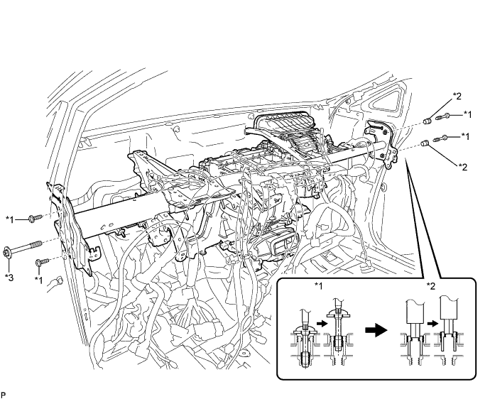
Text in Illustration *1 "TORX" Bolt *2 Collar *3 Bolt - - Tech Tips
The "TORX" bolts on the passenger side may be removed with the collars for adjustment.
-
Using a 12 mm hexagon wrench, remove the 2 collars.
-
Remove the bolt and instrument panel reinforcement assembly with air conditioning unit assembly.
-
-
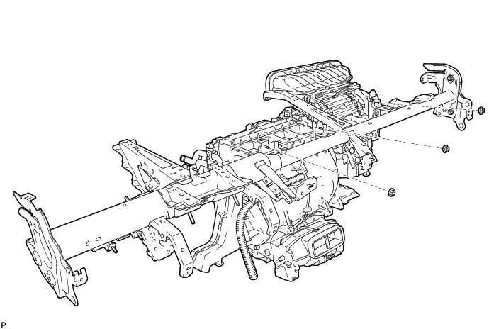
REMOVE AIR CONDITIONING UNIT ASSEMBLY
-
Remove the 3 nuts and air conditioning unit assembly from the instrument panel reinforcement assembly.
-