AIR CONDITIONING SYSTEM, Diagnostic DTC:B1412/12

| DTC Code | DTC Name |
|---|---|
| B1412/12 | Ambient Temperature Sensor Circuit |
DESCRIPTION
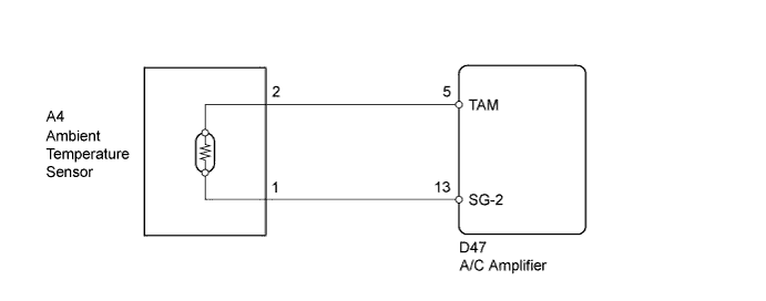
The ambient temperature sensor is installed in front of the condenser to detect the ambient temperature which is used to control the air conditioning system AUTO mode. This sensor is connected to the A/C amplifier and detects fluctuations in the ambient temperature. This data is used for controlling the cabin temperature. The sensor sends a signal to the A/C amplifier. The resistance of the ambient temperature sensor changes in accordance with the ambient temperature. As the temperature decreases, the resistance increases. As the temperature increases, the resistance decreases.
The A/C amplifier applies voltage (5 V) to the ambient temperature sensor and reads voltage changes as the resistance of the ambient temperature sensor changes.
| DTC No. | DTC Detection Condition | Trouble Area |
|---|---|---|
| B1412/12 | Open or short in ambient temperature sensor circuit |
|
WIRING DIAGRAM
INSPECTION PROCEDURE
PROCEDURE
-
READ VALUE USING GTS
-
Connect the GTS to the DLC3.
-
Turn the ignition switch to ON.
-
Turn the GTS on.
-
Enter the following menus: Body Electrical / Air Conditioner / Data List.
-
Check the value(s) by referring to the table below.
Air Conditioner Tester Display Measurement Item/Range Normal Condition Diagnostic Note Ambient Temp Sensor Ambient temperature sensor /
Min: -23.3°C (-9.94°F)
Max: 65.95°C (150.71°F)
Actual ambient temperature displayed - OK The display is as specified in the normal condition column. Result Result Proceed to NG A OK (When troubleshooting according to Problem Symptoms Table) B OK (When troubleshooting according to the DTC) C
B 
PROCEED TO NEXT SUSPECTED AREA SHOWN IN PROBLEM SYMPTOMS TABLE Click here
C
REPLACE A/C AMPLIFIER Click here
A 
-
-
INSPECT AMBIENT TEMPERATURE SENSOR
-
Remove the ambient temperature sensor.
-
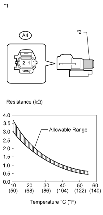
Text in Illustration *1 Component without harness connected
(Ambient Temperature Sensor)
*2 Sensing Portion Measure the resistance according to the value(s) in the table below.
Standard Resistance Tester Connection Condition Specified Condition A4-1 - A4-2 10°C (50°F) 3.00 to 3.73 kΩ A4-1 - A4-2 15°C (59°F) 2.45 to 2.88 kΩ A4-1 - A4-2 20°C (68°F) 1.95 to 2.30 kΩ A4-1 - A4-2 25°C (77°F) 1.60 to 1.80 kΩ A4-1 - A4-2 30°C (86°F) 1.28 to 1.47 kΩ A4-1 - A4-2 35°C (95°F) 1.00 to 1.22 kΩ A4-1 - A4-2 40°C (104°F) 0.80 to 1.00 kΩ A4-1 - A4-2 45°C (113°F) 0.65 to 0.85 kΩ A4-1 - A4-2 50°C (122°F) 0.50 to 0.70 kΩ A4-1 - A4-2 55°C (131°F) 0.44 to 0.60 kΩ A4-1 - A4-2 60°C (140°F) 0.36 to 0.50 kΩ Note
-
Hold the sensor only by its connector. Touching the sensing portion may change the resistance value.
-
When measuring, the sensor temperature must be the same as the ambient temperature.
Tech Tips
As the temperature increases, the resistance decreases (see the graph).
-
NG
REPLACE AMBIENT TEMPERATURE SENSOR Click here
OK
-
-
CHECK HARNESS AND CONNECTOR (AMBIENT TEMPERATURE SENSOR - A/C AMPLIFIER)
-
Disconnect the D47 A/C amplifier connector.
-
Measure the resistance according to the value(s) in the table below.
Standard Resistance Tester Connection Condition Specified Condition D47-5 (TAM) - A4-2 Always Below 1 Ω D47-13 (SG-2) - A4-1 Always Below 1 Ω D47-5 (TAM) - Body ground Always 10 kΩ or higher D47-13 (SG-2) - Body ground Always 10 kΩ or higher
NG
REPAIR OR REPLACE HARNESS OR CONNECTOR
OK 
REPLACE A/C AMPLIFIER Click here
-