AIR CONDITIONING SYSTEM DIAGNOSIS SYSTEM

-
DESCRIPTION
-
Air conditioning system data and Diagnostic Trouble Codes (DTCs) can be read through the Data Link Connector 3 (DLC3) of the vehicle. When the system seems to be malfunctioning, use the GTS to check for malfunctions and perform troubleshooting.
-
-
CHECK DLC3
-
Check the DLC3 Click here.
-
-
LIST OF OPERATION METHODS
-
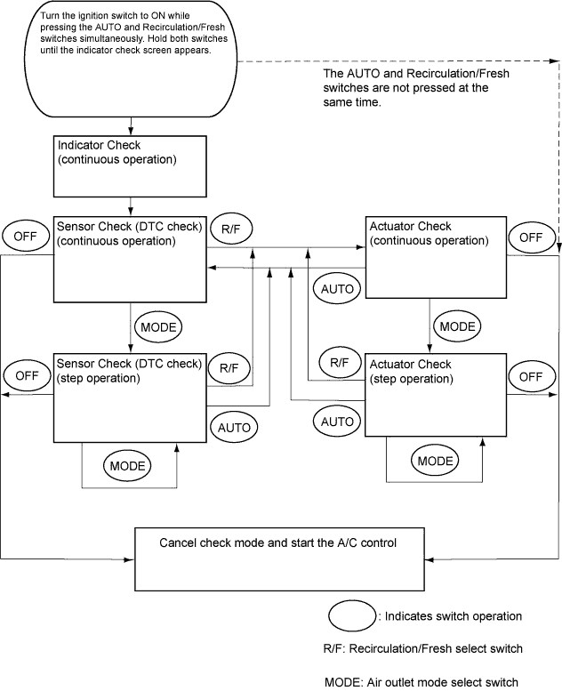
By operating each of the air conditioning control switches as shown in the diagram below, it is possible to enter diagnostic check mode.
-
-
INDICATOR CHECK
-
Turn the ignition switch off.
-
Turn the ignition switch to ACC and wait at least 5 seconds.
-
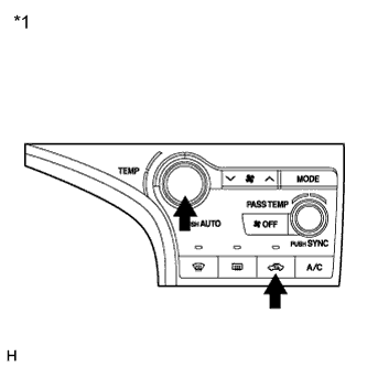
Text in Illustration *1 Air Conditioning Control Assembly Turn the ignition switch to ON while pressing the A/C control AUTO switch and recirculation/fresh switch simultaneously. Hold both switches until the indicator check screen appears.
-
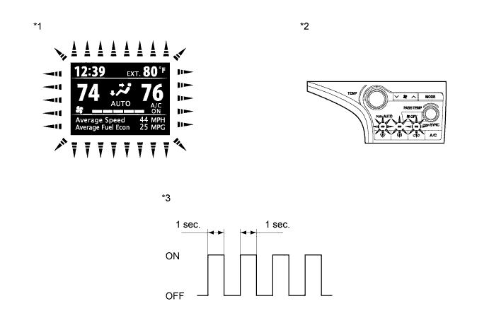
The indicator check is automatically performed when panel diagnosis is activated. Check that the indicators light up and go off 4 times at 1 second intervals continuously.
Tech Tips
-
The sensor check automatically starts when the indicator check is completed.
-
Press the OFF switch to cancel the check mode.
Text in Illustration *1 Accessory Meter Assembly *2 Air Conditioning Control Assembly *3 Indicator Blinking Pattern - - -
-
-
SENSOR CHECK (DTC CHECK)
-
Start the engine and warm it up.
-
Perform the indicator check.
Tech Tips
After the indicator check is completed, the system enters DTC check mode automatically.
-
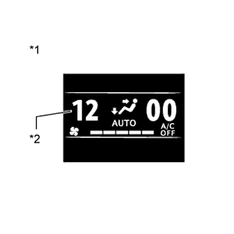
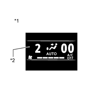
Text in Illustration *1 Accessory Meter Assembly *2 Diagnostic Trouble Code (DTC) Read the DTCs displayed on the accessory meter assembly display.
Note
In sensor check mode, which is automatically entered after indicator check mode, troubleshooting may be partially performed. Be sure to perform the actuator check, and then the sensor check again.
Tech Tips
Refer to Diagnostic Trouble Code Chart for details of the codes Click here.
-
When there are no problems, DTC 00 is output.
-
As an example, the illustration shows that display DTC 12 is output.
-
-

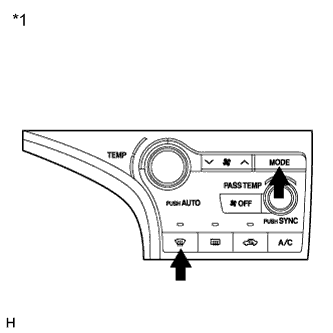
Text in Illustration *1 Air Conditioning Control Assembly If the steps are difficult to read because they change automatically, press the MODE switch to display the steps one at a time so that they can be read easily. The items are displayed step by step each time the MODE switch is pressed.
Tech Tips
-
Press the OFF switch to finish panel diagnosis.
-
Press the recirculation/fresh switch to enter actuator check mode.
-
-
Clear the DTC
-
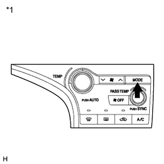
Text in Illustration *1 Air Conditioning Control Assembly During the sensor check, press the defroster switch and MODE switch simultaneously.
-
-
-
ACTUATOR CHECK
-
Start the engine and warm it up.
-
Perform the indicator check.
-
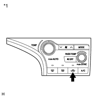
Text in Illustration *1 Air Conditioning Control Assembly Press the recirculation/fresh switch to perform the actuator check.
Tech Tips
Be sure to perform the actuator check after starting the engine.
-
Text in Illustration *1 Accessory Meter Assembly *2 Display Code As the actuator check is repeated from steps 1 to 10 at 1 second intervals, check the temperature and air flow visually and by hand.
Tech Tips
-
The display blinks at 1 second intervals in the step operation.
-
Press the OFF switch to finish panel diagnosis.
-
Press the AUTO switch to enter sensor check mode.
Step No. Display Code Condition Blower Level Air Mix Damper Airflow Vent Air Inlet Damper Compressor 1 0 0 0% open FACE FRESH off 2 1 1 0% open FACE FRESH off 3 2 17 0% open FACE RECIRCULATION / FRESH on 4 3 17 0% open FACE RECIRCULATION on 5 4 17 50% open B/L RECIRCULATION on 6 5 17 50% open B/L RECIRCULATION on 7 6 17 50% open FOOT FRESH on 8 7 17 100% open FOOT-0 FRESH on 9 8 17 100% open F/D FRESH on 10 9 31 100% open DEF FRESH on -
-
Text in Illustration *1 Air Conditioning Control Assembly If the steps are difficult to read because they change automatically, press the MODE switch to display the steps one at a time so that they can be read easily. The items are displayed step by step each time the MODE switch is pressed.
Tech Tips
-
Press the OFF switch to finish panel diagnosis.
-
Press the recirculation/fresh switch to enter sensor check mode.
-
-