COMPRESSOR INSTALLATION

-
ADJUST COMPRESSOR OIL LEVEL
-
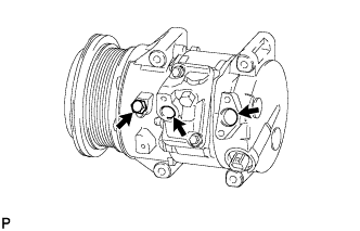
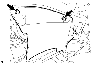
When replacing the cooler compressor assembly with a new one, gradually discharge the inert gas (helium) from the service valve, and drain the following amount of oil from the vents indicated by the arrows in the illustration before installation.
Tech Tips
The drain bolt and washer can be reused.
Standard (Oil capacity inside the new compressor assembly with pulley: 130 + 15 cc (4.4 + 0.51 fl.oz.) ) - (Remaining oil amount in the removed compressor assembly with pulley) = (Oil amount to be removed from the new compressor when replacing) Note
-
If a new compressor is installed without removing some oil remaining in the pipes of the vehicle, the oil amount will be excessive. This prevents heat exchange in the refrigerant cycle and causes refrigeration system failure.
-
If the volume of oil remaining in the removed compressor is too small, check for oil leaks.
-
Be sure to use ND-OIL 8 or equivalent for compressor oil.
-
-
-
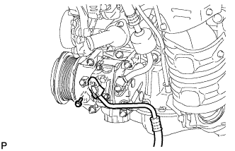
INSTALL COMPRESSOR ASSEMBLY WITH PULLEY
-
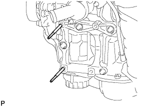
Using an E8 "TORX" socket wrench, install the 2 stud bolts.
- Torque:
- 10 N*m { 102 kgf*cm, 7 ft.*lbf }
-
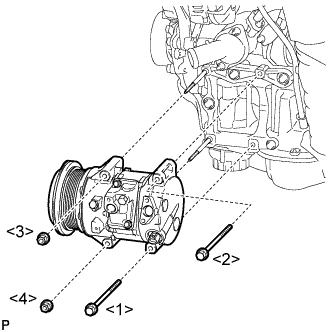
Install the compressor assembly with pulley with the 2 bolts and 2 nuts.
- Torque:
- 25 N*m { 255 kgf*cm, 18 ft.*lbf }
Note
Tighten the bolts and nuts in the order shown in the illustration to install the compressor assembly with pulley.
-
-
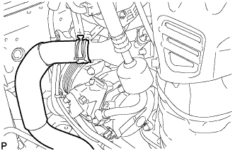
CONNECT SUCTION HOSE SUB-ASSEMBLY
-
Remove the attached vinyl tape from the hose.
-
Apply sufficient compressor oil to a new O-ring and the fitting surface of the compressor assembly with pulley.
Compressor oil ND-OIL 8 or equivalent -
Install the O-ring onto the suction hose sub-assembly.
Note
Keep the O-ring and O-ring fitting surfaces free from dirt or any foreign objects.
-
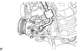
Install the suction hose sub-assembly onto the compressor assembly with pulley with the bolt.
- Torque:
- 9.8 N*m { 100 kgf*cm, 87 in.*lbf }
-
-
CONNECT COOLER REFRIGERANT DISCHARGE HOSE
-
Remove the attached vinyl tape from the hose.
-
Apply sufficient compressor oil to a new O-ring and the fitting surface of the compressor assembly with pulley.
Compressor oil ND-OIL 8 or equivalent -
Install the O-ring onto the discharge hose.
Note
Keep the O-ring and O-ring fitting surfaces free from dirt or any foreign objects.
-
Install the cooler refrigerant discharge hose onto the compressor assembly with pulley with the bolt.
- Torque:
- 9.8 N*m { 100 kgf*cm, 87 in.*lbf }
-
Using pliers, grip the claws of the clip and slide the clip to install the No. 2 radiator hose.
-
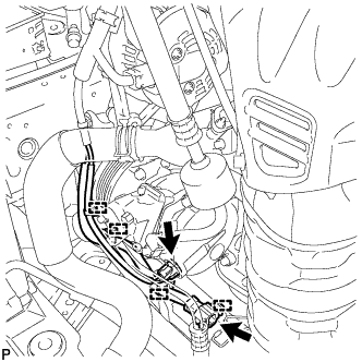
Engage each clamp.
-
Connect each connector.
-
-
INSTALL RADIATOR ASSEMBLY
Tech Tips
Refer to the procedure for Install Radiator Assembly Click here.
-
INSTALL V-RIBBED BELT
-
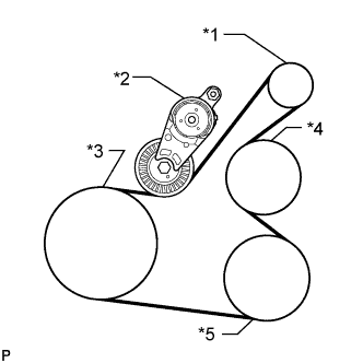
Text in Illustration *1 Generator *2 Tensioner *3 Crankshaft *4 Water Pump *5 Cooler Compressor Set the V-ribbed belt onto each part as shown in the illustration except the water pump pulley.
-
Loosen the V-ribbed belt by turning the belt tensioner clockwise.
-
Set the V-ribbed belt onto the water pump pulley.
Note
Make sure that the belt is attached to each pulley. In particular, make sure that the belt is securely fitted into the grooves of the crankshaft pulley.
-
-
INSTALL FRONT FENDER APRON SEAL RH
-
Install the front fender apron seal RH with the 2 bolts and clip.
-
-
INSTALL FRONT FENDER LINER RH
-
INSTALL FRONT WHEEL RH
- Torque:
- 103 N*m { 1050 kgf*cm, 76 ft.*lbf }
-
CONNECT CABLE TO NEGATIVE BATTERY TERMINAL
Note
When disconnecting the cable, some systems need to be initialized after the cable is reconnected Click here.
-
CHARGE WITH REFRIGERANT
-
Perform vacuum purging using a vacuum pump.
-
Charge with refrigerant HFC-134a (R134a).
Standard 450 to 550 g (15.9 to 19.4 oz.) - SST
- 09985-20010 ( 09985-02010, 09985-02050, 09985-02060, 09985-02070, 09985-02080, 09985-02090, 09985-02110, 09985-02130, 09985-02140, 09985-02150 )
Note
Do not turn the A/C switch on before charging with refrigerant. Doing so will cause the compressor to work without refrigerant, resulting in overheating of the compressor.
Tech Tips
Ensure that sufficient refrigerant is available to recharge the system when using a refrigerant recovery unit. Refrigerant recovery units are not always able to recover 100% of the refrigerant from an A/C system.
-
-
WARM UP ENGINE
-
Keep the A/C switch on for at least 2 minutes to warm up the compressor.
Note
Be sure to warm up the compressor when turning the A/C switch on after removing and installing the cooler refrigerant lines (including the compressor), to prevent damage to the compressor.
-
-
INSPECT FOR REFRIGERANT LEAK
-
After recharging with refrigerant, inspect for refrigerant leaks using a halogen leak detector.
-
Carry out the test under the following conditions:
-
Turn the ignition switch off.
-
Secure good ventilation (the halogen leak detector may react to volatile gases which are not refrigerant, such as evaporated gasoline and exhaust gas).
-
Repeat the test 2 or 3 times.
-
Make sure that there is some refrigerant remaining in the refrigeration system.
When the compressor is off: approx. 392 to 588 kPa (4.0 to 6.0 kgf/cm2, 57 to 85 psi)
-
-
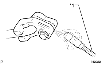
Text in Illustration *1 Halogen Leak Detector Using a halogen leak detector, inspect for refrigerant leaks from the refrigerant lines.
-
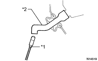
Text in Illustration *1 Halogen Leak Detector *2 Drain Hose Bring the halogen leak detector close to the drain hose with the detector's power off, and then turn the detector on.
Tech Tips
-
After the blower motor has stopped, let the cooling unit stand for more than 15 minutes.
-
Bring the halogen leak detector sensor under the drain hose.
-
When bringing the halogen leak detector close to the drain hose, make sure that the halogen leak detector does not react to volatile gases. If it is not possible to avoid interference from volatile gases, the vehicle should be lifted up to allow testing.
-
-
If a refrigerant leak is not detected from the drain hose, remove the blower motor control from the cooling unit. Insert the halogen leak detector sensor into the unit and perform the test.
-
Disconnect the pressure switch connector and leave it for approximately 20 minutes. Bring the halogen leak detector close to the pressure switch and perform the test.
-
-
INSTALL NO. 1 ENGINE UNDER COVER