LUMBAR SUPPORT ADJUSTER ASSEMBLY INSTALLATION

-
INSTALL LUMBAR SUPPORT ADJUSTER ASSEMBLY
-
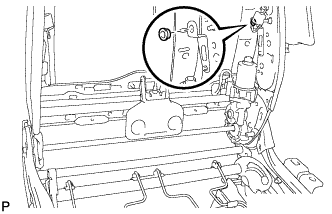
Install the bush.
-
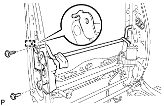
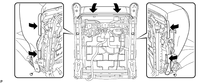
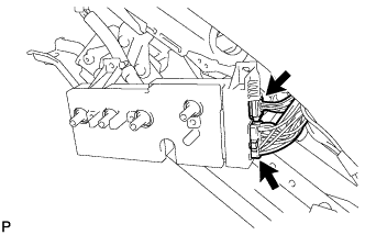
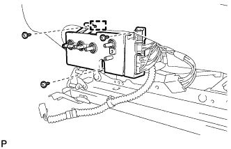
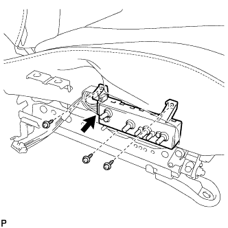
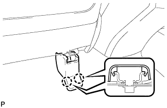
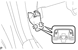
Install the lumbar support adjuster assembly with the guide and 2 screws.
-
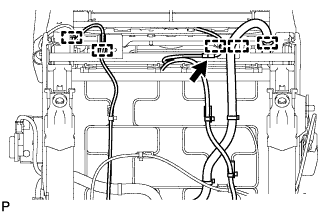
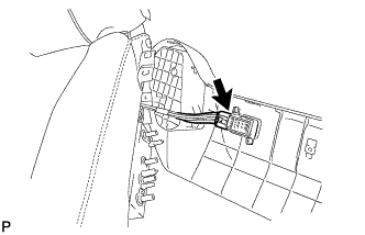
Connect the connector.
-
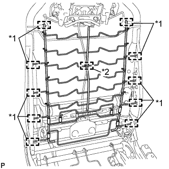
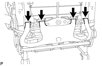
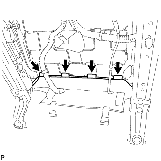
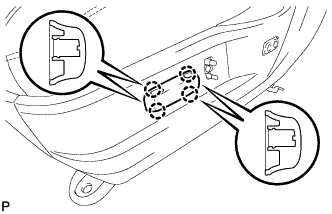
Text in Illustration *1 Guide *2 Clamp Install the front seatback spring sub-assembly with the 8 guides and a new clamp.
-
-
INSTALL SEPARATE TYPE FRONT SEATBACK COVER WITH PAD
-
Temporarily install the separate type front seatback cover with pad to the front seat frame assembly with adjuster.
-
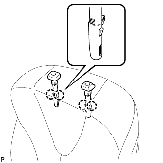
Engage the 4 claws and install the 2 front seat headrest supports.
-

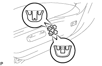
Using hog ring pliers, install 2 new hog rings.
Note
-
Be careful not to damage the separate type front seatback cover.
-
Be sure to securely install the hog rings as shown in the illustration while preventing wrinkles from forming on the separate type front seatback cover.
-
-

Using hog ring pliers, install 2 new hog rings.
Note
-
Be careful not to damage the separate type front seatback cover.
-
Be sure to securely install the hog rings as shown in the illustration while preventing wrinkles from forming on the separate type front seatback cover.
-
-
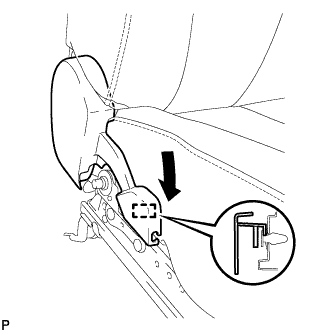
Engage the 4 hooks.
-
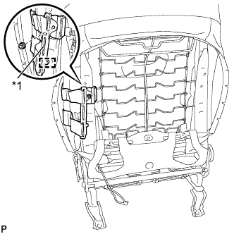
Text in Illustration *1 Bracket Engage the guide to install the bracket of the separate type front seatback cover with the nut.
- Torque:
- 8.0 N*m { 82 kgf*cm, 71 in.*lbf }
Note
-
For vehicles with front seat side airbag assembly, the front seat side airbag assembly may not be activated normally unless the separate type front seatback cover is securely installed.
-
Check that the strap is not twisted after installing the bracket.
-
Install the bracket securely.
-
-
INSTALL FRONT SEATBACK BOARD SUB-ASSEMBLY
-

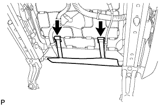
Engage the 2 guides as shown in the illustration.
-

Engage the 14 claws.
-
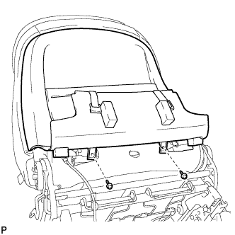
Install the front seatback board sub-assembly with the 2 screws.
-
-
INSTALL SEPARATE TYPE FRONT SEAT CUSHION COVER WITH PAD
-
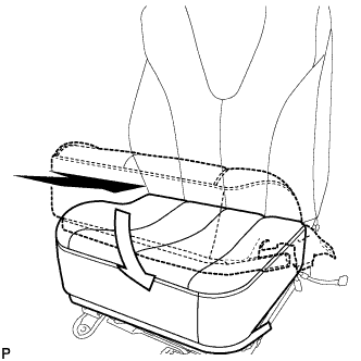
Temporarily install the separate type front seat cushion cover with pad to the front seat frame assembly with adjuster.
-
Engage each hook as shown in the illustration.
-
Install the 2 clips.
-
Connect the connector.
-
Engage each clamp.
-
Engage the 4 hooks and install the separate type front seat cushion cover with pad.
-
-
INSTALL FRONT INNER SEAT CUSHION SHIELD
-
Engage the guide as shown in the illustration.
-
Engage the claw.
-
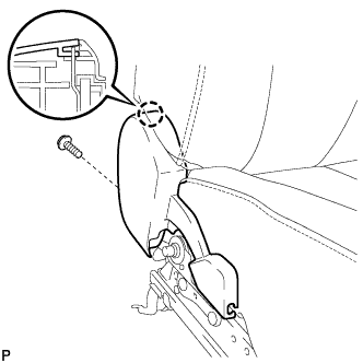
Install the front inner seat cushion shield with the screw.
-
-
INSTALL FRONT SEAT INNER BELT ASSEMBLY
-
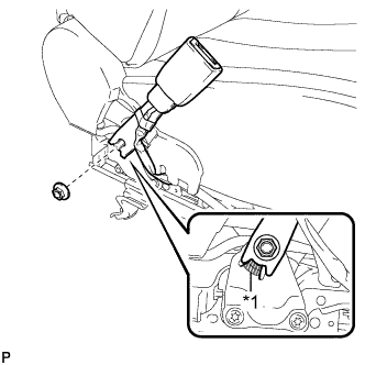
Text in Illustration *1 Protruding Part Install the front seat inner belt assembly with the nut.
- Torque:
- 42 N*m { 428 kgf*cm, 31 ft.*lbf }
Note
Do not allow the anchor part of the front seat inner belt assembly to overlap the protruding part of the front seat adjuster.
-
Connect each connector and engage each clamp.
-
-
INSTALL POSITION CONTROL ECU AND SWITCH ASSEMBLY (for Driver Side)
-
Connect the 2 connectors.
-
Engage the guide.
-
Install the position control ECU and switch assembly with the 3 screws.
-
-
INSTALL FRONT POWER SEAT SWITCH RH (for Front Passenger Side)
-
Connect the connector.
-
Install the front power seat switch RH with the 3 screws.
-
-
INSTALL FRONT SEAT CUSHION SHIELD ASSEMBLY
-
Connect the connector to the front power seat lumbar switch.
-
Engage the guide and claw.
-
Install the front seat cushion shield assembly with the 5 screws.
-
Engage the 2 hooks.
-
-
INSTALL SLIDE AND VERTICAL POWER SEAT SWITCH KNOB
-
Engage the 4 claws to install the slide and vertical power seat switch knob.
-
-
INSTALL RECLINING POWER SEAT SWITCH KNOB
-
Engage the 4 claws to install the reclining power seat switch knob.
-
-
INSTALL FRONT SEAT ASSEMBLY
-
Place the front seat assembly in the cabin.
Note
Be careful not to damage the vehicle body.
-
Connect each connector under the front seat assembly.
-
Connect the cable to the negative (-) battery terminal.
Note
When disconnecting the cable, some systems need to be initialized after the cable is reconnected Click here.
-
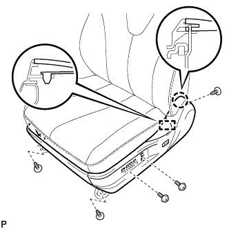
Temporarily install the front seat assembly with the 4 bolts.
-
Operate the slide and vertical power seat switch knob and move the seat to the rearmost position.
-
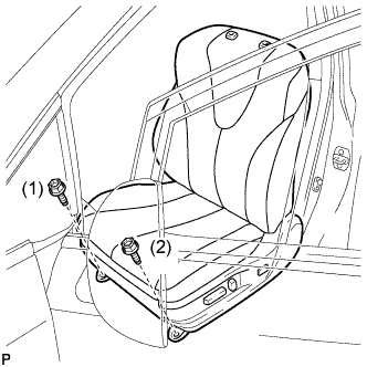
Tighten the 2 bolts on front side of the front seat assembly.
- Torque:
- 37 N*m { 377 kgf*cm, 27 ft.*lbf }
Tech Tips
Tighten the bolts in the order indicated in the illustration.
-
Operate the slide and vertical power seat switch knob and move the front seat assembly to the foremost position.
-
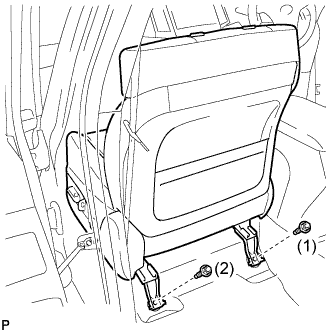
Tighten the 2 bolts on rear side of the front seat assembly.
- Torque:
- 37 N*m { 377 kgf*cm, 27 ft.*lbf }
Tech Tips
Tighten the bolts in the order indicated in the illustration.
-
-
INSTALL FRONT SEAT REAR INNER TRACK COVER
-
Engage the 2 claws to install the front seat rear inner track cover.
-
-
INSTALL FRONT SEAT REAR OUTER TRACK COVER
-
Engage the 2 claws to install the front seat rear outer track cover.
-
-
INSTALL FRONT SEAT HEADREST ASSEMBLY
-
INSPECT FRONT SEAT ASSEMBLY
-
Inspect the power seat operation.
-
Check the seat heater operation.
-
Turn the ignition switch to ON.
-
Turn the seat heater switch on.
-
Wait 5 minutes or more and confirm that the seat surface becomes warm.
-
-
-
INSPECT SRS WARNING LIGHT