FRONT POWER SEAT CONTROL SYSTEM (w/ Memory) One or more Power Seat Motors do not Operate
DESCRIPTION
Signals are input into the position control ECU and switch assembly. The built-in ECU manages the signals received from the position control ECU and switch assembly, and operates each motor. If the position control ECU and switch assembly receives more than 2 motor operation signals, the motor is stopped. Manual operation is restarted after the position control ECU and switch assembly receives 1 signal only.
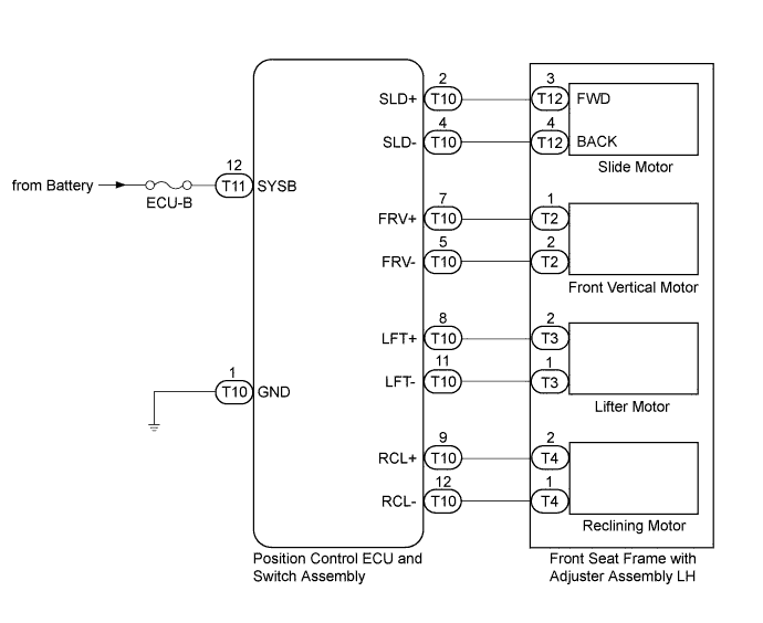
WIRING DIAGRAM
INSPECTION PROCEDURE
Note
Inspect the fuses for circuits related to this system before performing the following inspection procedure.
PROCEDURE
-
READ VALUE USING GTS (POWER SEAT SWITCH)
-
Connect the GTS to the DLC3.
-
Turn the ignition switch to ON.
-
Turn the GTS on.
-
Enter the following menus: Body Electrical / Driver Seat / Data List.
-
Read the Data List according to the display on the GTS.
Driver Seat Tester Display Measurement Item/Range Normal Condition Diagnostic Note Reclining Rear Reclining switch signal (Rearward) / ON or OFF ON: Reclining switch (Rearward) on
OFF: Reclining switch (Rearward) off
- Reclining Front Reclining switch signal (Forward) / ON or OFF ON: Reclining switch (Forward) on
OFF: Reclining switch (Forward) off
- Front Vertical Down Front vertical switch signal (Downward) / ON or OFF ON: Front vertical switch (Downward) on
OFF: Front vertical switch (Downward) off
- Front Vertical Up Front vertical switch signal (Upward) / ON or OFF ON: Front vertical switch (Upward) on
OFF: Front vertical switch (Upward) off
- Lifter Switch Down Lifter switch signal (Downward) / ON or OFF ON: Lifter switch (Downward) on
OFF: Lifter switch (Downward) off
- Lifter Switch Up Lifter switch signal (Upward) / ON or OFF ON: Lifter switch (Upward) on
OFF: Lifter switch (Upward) off
- Slide Rear Sliding switch signal (Rearward) / ON or OFF ON: Sliding switch (Rearward) on
OFF: Sliding switch (Rearward) off
- Slide Front Sliding switch signal (Forward) / ON or OFF ON: Sliding switch (Forward) on
OFF: Sliding switch (Forward) off
- OK ON or OFF is displayed on the GTS according to the table above.
NG 
CHECK HARNESS AND CONNECTOR (BATTERY - POSITION CONTROL ECU AND SWITCH ASSEMBLY - BODY GROUND) Click here
OK 
-
-
PERFORM ACTIVE TEST USING GTS (POWER SEAT MOTOR)
-
Enter the following menus: Body Electrical / Driver Seat / Active Test.
-
Perform the Active Test according to the display on the GTS.
Driver Seat Tester Display Test Part Control Range Diagnostic Note Seat Reclining Seat reclining operation OFF/Front/Rear - Front Vertical Operation Seat front vertical operation OFF/Up/Down - Lifter Operation Seat lifter operation OFF/Up/Down - Seat Slide Operation Seat sliding operation OFF/Front/Rear - OK The power seat motors operate normally.
NG
INSPECT FRONT SEAT FRAME WITH ADJUSTER ASSEMBLY LH Click here
OK 
REPLACE POSITION CONTROL ECU AND SWITCH ASSEMBLY Click here
-
-
INSPECT FRONT SEAT FRAME WITH ADJUSTER ASSEMBLY LH
-
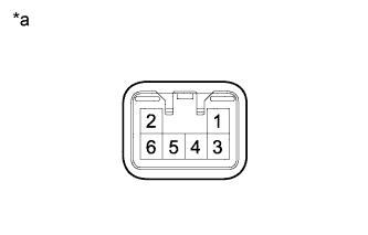
Text in Illustration *a Component without harness connected
(Slide Motor (Front Seat Frame with Adjuster Assembly LH))
Remove the front seat frame with adjuster assembly LH Click here.
-
Check operation of the slide motor.
-
Check if the seat moves smoothly when the battery is connected to the slide motor connector terminals.
OK Condition Specified Condition Battery positive (+) → Terminal 3
Battery negative (-) → Terminal 4
Forward Battery positive (+) → Terminal 4
Battery negative (-) → Terminal 3
Rearward
-
-
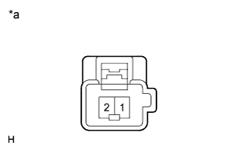
Text in Illustration *a Component without harness connected
(Front Vertical Motor (Front Seat Frame with Adjuster Assembly LH))
Check operation of the front vertical motor.
-
Check if the seat moves smoothly when the battery is connected to the front vertical motor connector terminals.
OK Condition Specified Condition Battery positive (+) → Terminal 1
Battery negative (-) → Terminal 2
Upward Battery positive (+) → Terminal 2
Battery negative (-) → Terminal 1
Downward
-
-
Text in Illustration *a Component without harness connected
(Lifter Motor (Front Seat Frame with Adjuster Assembly LH))
Check operation of the lifter motor.
-
Check if the seat moves smoothly when the battery is connected to the lifter motor connector terminals.
OK Condition Specified Condition Battery positive (+) → Terminal 2
Battery negative (-) → Terminal 1
Upward Battery positive (+) → Terminal 1
Battery negative (-) → Terminal 2
Downward
-
-
Text in Illustration *a Component without harness connected
(Reclining Motor (Front Seat Frame with Adjuster Assembly LH))
Check operation of the reclining motor.
-
Check if the seat moves smoothly when the battery is connected to the reclining motor connector terminals.
OK Condition Specified Condition Battery positive (+) → Terminal 2
Battery negative (-) → Terminal 1
Forward Battery positive (+) → Terminal 1
Battery negative (-) → Terminal 2
Rearward
-
NG 
REPLACE FRONT SEAT FRAME WITH ADJUSTER ASSEMBLY LH Click here
OK
-
-
CHECK HARNESS AND CONNECTOR (POSITION CONTROL ECU AND SWITCH ASSEMBLY - POWER SEAT MOTOR)
-
Disconnect the T10 position control ECU and switch assembly connector.
-
Measure the resistance according to the value(s) in the table below.
Standard Resistance Tester Connection Condition Specified Condition T10-2 (SLD+) - T12-3 (FWD) Always Below 1 Ω T10-4 (SLD-) - T12-4 (BACK) Always Below 1 Ω T10-5 (FRV-) - T2-2 Always Below 1 Ω T10-7 (FRV+) - T2-1 Always Below 1 Ω T10-8 (LFT+) - T3-2 Always Below 1 Ω T10-11 (LFT-) - T3-1 Always Below 1 Ω T10-9 (RCL+) - T4-2 Always Below 1 Ω T10-12 (RCL-) - T4-1 Always Below 1 Ω T10-2 (SLD+) - Body ground Always 10 kΩ or higher T10-4 (SLD-) - Body ground Always 10 kΩ or higher T10-5 (FRV-) - Body ground Always 10 kΩ or higher T10-7 (FRV+) - Body ground Always 10 kΩ or higher T10-8 (LFT+) - Body ground Always 10 kΩ or higher T10-11 (LFT-) - Body ground Always 10 kΩ or higher T10-9 (RCL+) - Body ground Always 10 kΩ or higher T10-12 (RCL-) - Body ground Always 10 kΩ or higher
NG
REPAIR OR REPLACE HARNESS OR CONNECTOR
OK
REPLACE POSITION CONTROL ECU AND SWITCH ASSEMBLY Click here
-
-
CHECK HARNESS AND CONNECTOR (BATTERY - POSITION CONTROL ECU AND SWITCH ASSEMBLY - BODY GROUND)
-
Disconnect the T11 position control ECU and switch assembly connector.
-
Measure the voltage and resistance according to the value(s) in the table below.
Standard Voltage Tester Connection Condition Specified Condition T11-12 (SYSB) - Body ground Always 11 to 14 V Standard Resistance Tester Connection Condition Specified Condition T10-1 (GND) - Body ground Always Below 1 Ω
NG
REPAIR OR REPLACE HARNESS OR CONNECTOR
OK
REPLACE POSITION CONTROL ECU AND SWITCH ASSEMBLY Click here
-