REAR AIRBAG SENSOR INSTALLATION

Tech Tips
-
Use the same procedure for the RH side and LH side.
-
The procedure listed below is for the LH side.
-
INSTALL REAR AIRBAG SENSOR
-
Check that the ignition switch is off.
-
Check that the cable is disconnected from the negative (-) battery terminal.
CAUTION:
Wait at least 90 seconds after disconnecting the cable from the negative (-) battery terminal to disable the SRS system.
-
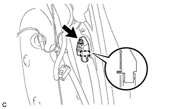
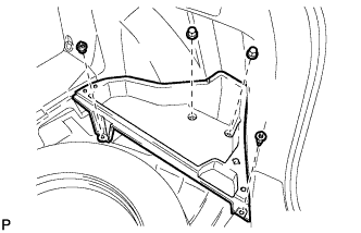
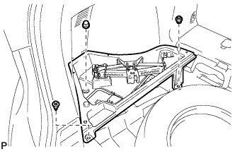
Insert the pin (stopper) into the body hole and install the rear airbag sensor with the nut.
- Torque:
- 9.0 N*m { 92 kgf*cm, 80 in.*lbf }
Note
-
If the rear airbag sensor has been dropped, or there are any cracks, dents or other defects in the case or connector, replace it with a new one.
-
When installing the rear airbag sensor, be careful that the SRS wiring does not interfere with or is not pinched between other parts.
-
Make sure that the pin (stopper) is securely inserted into the body hole.
-
Tighten the nut while holding the rear airbag sensor because the rear airbag sensor pin (stopper) is easily damaged.
-
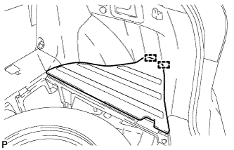
Connect the connector to the rear airbag sensor assembly.
Note
When connecting the airbag connector, take care not to damage the airbag wire harness.
-
Connect the connector as shown in the illustration (when locking, make sure that the outer connector locking sleeve returns to its original position and a click sound can be heard).
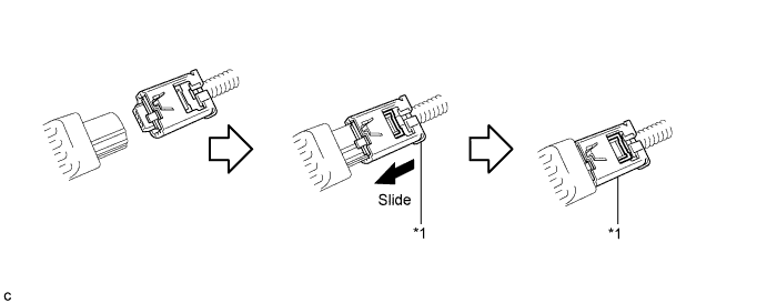
Text in Illustration *1 Outer Connector Locking Sleeve - - Tech Tips
When connected, the outer connector locking sleeve will slide. Be sure not to hold the outer connector locking sleeve while connecting, as it may result in an insecure fit.
-
-
Check that there is no looseness in the installation parts of the rear airbag sensor.
-
-
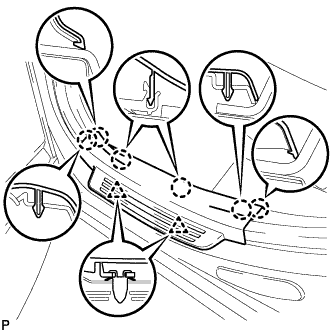
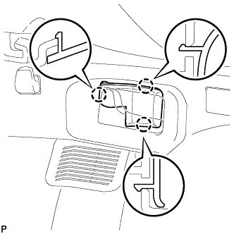
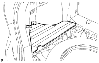
INSTALL DECK TRIM SIDE PANEL ASSEMBLY
-
Connect the connector.
-
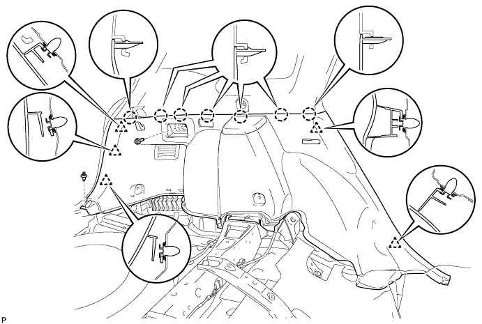
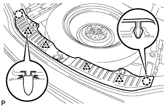
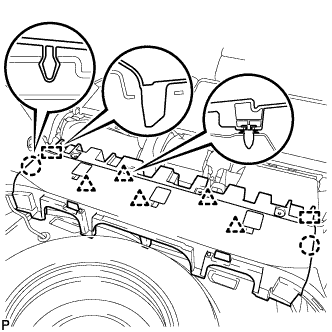
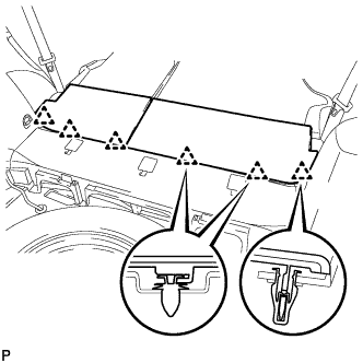
Engage the 7 claws and the 5 clips.
-
Install the deck trim side panel assembly LH with the bolt and clip.
-
-
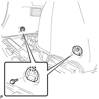
CONNECT REAR SEAT OUTER BELT ASSEMBLY
-
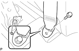
Text in Illustration *1 Protruding Part Connect the floor anchor end of the rear seat outer belt assembly and install the bolt.
- Torque:
- 42 N*m { 428 kgf*cm, 31 ft.*lbf }
Note
Do not allow the anchor part of the rear seat outer belt assembly to overlap the protruding part of the floor panel.
-
-
INSTALL REAR DOOR OPENING TRIM WEATHERSTRIP
-
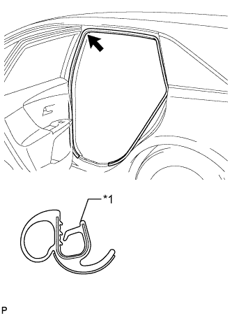
Text in Illustration *1 Alignment mark (Purple) Align the alignment mark (Purple) on the weatherstrip with the protruding portion on the body indicated by the arrow in the illustration, and install the rear door opening trim weatherstrip LH.
Note
After installation, check that the corners fit correctly.
-
-
INSTALL REAR DOOR SCUFF PLATE
-
Engage the 2 clips and 6 claws to install the rear door scuff plate LH.
-
-
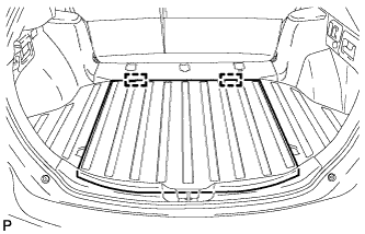
INSTALL LUGGAGE HOLD BELT STRIKER ASSEMBLY
-
Engage the 2 guides.
-
Install the 2 luggage hold belt striker assemblies with the 2 bolts.
-
-
INSTALL RECLINING REMOTE CONTROL BEZEL
-
Engage the 3 claws to install the reclining remote control bezel LH.
-
-
INSTALL REAR FLOOR FINISH PLATE
-
Engage the 4 clips and 2 claws to install the rear floor finish plate.
-
-
INSTALL REAR SEAT SUB FLOOR PANEL ASSEMBLY
-
Engage the 2 guides, 2 claws and 5 clips to install the rear seat sub floor panel assembly.
-
-
INSTALL NO. 1 DECK BOARD
-
Engage the 6 clips to install the No. 1 deck board.
-
-
INSTALL DECK SIDE TRIM BOX RH
-
Install the deck side trim box RH with the 4 clips.
-
-
INSTALL NO. 2 DECK BOARD SUB-ASSEMBLY
-
Engage the 2 guides to install the No. 2 deck board sub-assembly.
-
-
INSTALL DECK SIDE TRIM BOX LH
-
Install the deck side trim box LH with the 3 clips.
-
-
INSTALL NO. 3 DECK BOARD SUB-ASSEMBLY
-
Engage the 2 guides to install the No. 3 deck board sub-assembly.
-
-
INSTALL DECK BOARD ASSEMBLY
-
Engage the 2 guides to install the deck board assembly.
-
-
INSTALL TONNEAU COVER ASSEMBLY
-
Install the tonneau cover assembly.
-
-
CONNECT CABLE TO NEGATIVE BATTERY TERMINAL
Note
When disconnecting the cable, some systems need to be initialized after the cable is reconnected Click here.
-
PERFORM DIAGNOSTIC SYSTEM CHECK
-
Perform a diagnostic system check Click here.
-
-
INSPECT SRS WARNING LIGHT
-
Inspect the SRS warning light Click here.
-