OCCUPANT CLASSIFICATION SYSTEM, Diagnostic DTC:B1790

| DTC Code | DTC Name |
|---|---|
| B1790 | Center Airbag Sensor Assembly Communication Circuit Malfunction |
DESCRIPTION
The center airbag sensor assembly communication circuit consists of the occupant classification ECU and center airbag sensor assembly.
DTC B1790 is recorded when a malfunction is detected in the center airbag sensor assembly communication circuit.
| DTC No. | DTC Detecting Condition | Trouble Area |
|---|---|---|
| B1790 |
|
|
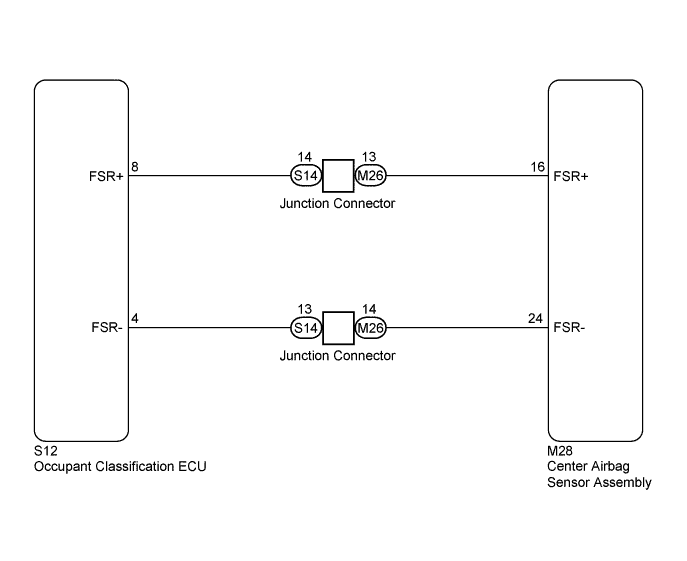
WIRING DIAGRAM
INSPECTION PROCEDURE
Tech Tips
-
If troubleshooting (wire harness inspection) is difficult to perform, remove the front passenger seat installation bolts to see the under surface of seat cushion.
-
In the above case, hold the seat so that it does not fall down. Holding the seat for a long period of time may cause a problem, such as seat rail deformation. Hold the seat only as necessary.
PROCEDURE
-
CHECK CONNECTORS
-
Turn the ignition switch off.
-
Disconnect the cable from the negative (-) battery terminal, and wait for at least 90 seconds.
-
Check that the connectors are properly connected to the center airbag sensor assembly and occupant classification ECU. Also check that the connectors that link the front seat wire RH and No. 2 floor wire are properly connected.
OK The connectors are properly connected. Tech Tips
If the connectors are not connected securely, reconnect the connectors and proceed to the next inspection.
-
Disconnect the connectors from the center airbag sensor assembly and occupant classification ECU. Also disconnect the connectors that link the front seat wire RH and No. 2 floor wire.
-
Check that the connector terminals are not damaged.
OK The terminals are not deformed or damaged.
NG 
REPLACE WIRE HARNESS
OK 
-
-
CHECK OCCUPANT CLASSIFICATION SYSTEM CIRCUIT (OPEN)
-
Turn the ignition switch off.
-
Disconnect the cable from the negative (-) battery terminal, and wait for at least 90 seconds.
-
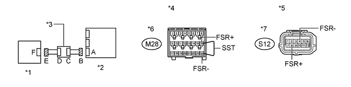
Using SST, connect terminals 16 (FSR+) and 24 (FSR-) of connector B.
Note
Do not forcibly insert SST wire into the terminals of the connector when connecting.
-
Measure the resistance according to the value(s) in the table below.
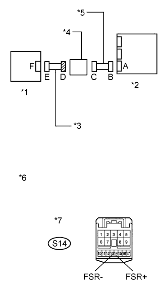
Standard Resistance Tester Connection Condition Specified Condition S12-8 (FSR+) - S12-4 (FSR-) Always Below 1 Ω Text in Illustration *1 Occupant Classification ECU *2 Center Airbag Sensor Assembly *3 Junction Connector *4 Front view of wire harness connector
(to Center Airbag Sensor Assembly)
*5 Front view of wire harness connector
(to Occupant Classification ECU)
*6 Connector B *7 Connector E - -
NG 
CHECK NO. 2 FLOOR WIRE (OPEN) Click here
OK
-
-
CHECK OCCUPANT CLASSIFICATION SYSTEM CIRCUIT (SHORT)
-
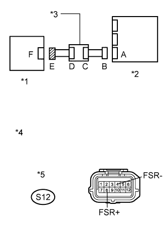
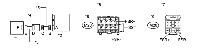
Text in Illustration *1 Occupant Classification ECU *2 Center Airbag Sensor Assembly *3 Junction Connector *4 Front view of wire harness connector
(to Occupant Classification ECU)
*5 Connector E Disconnect SST from connector B.
-
Measure the resistance according to the value(s) in the table below.
Standard Resistance Tester Connection Condition Specified Condition S12-8 (FSR+) - S12-4 (FSR-) Always 1 MΩ or higher
NG
CHECK FRONT SEAT WIRE RH (OPEN) Click here
OK
-
-
CHECK OCCUPANT CLASSIFICATION SYSTEM CIRCUIT (SHORT TO GROUND)
-
Text in Illustration *1 Occupant Classification ECU *2 Center Airbag Sensor Assembly *3 Junction Connector *4 Front view of wire harness connector
(to Occupant Classification ECU)
*5 Connector E Measure the resistance according to the value(s) in the table below.
Standard Resistance Tester Connection Condition Specified Condition S12-8 (FSR+) - Body ground Always 1 MΩ or higher S12-4 (FSR-) - Body ground Always 1 MΩ or higher
NG
CHECK NO. 2 FLOOR WIRE (SHORT) Click here
OK
-
-
RECHECK DTC
-
Connect the connectors to the occupant classification ECU and center airbag sensor assembly.
-
Connect the GTS to the DLC3.
-
Connect the cable to the negative (-) battery terminal.
-
Turn the ignition switch to ON.
-
Clear the DTCs stored in the occupant classification ECU Click here.
-
Clear the DTCs stored in the center airbag sensor assembly Click here.
-
Turn the ignition switch off.
-
Turn the ignition switch to ON.
-
Using the GTS, check the DTCs of the occupant classification ECU Click here.
OK DTC B1790 is not output. Tech Tips
Codes other than DTC B1790 may be output at this time, but they are not related to this check.
NG
REPLACE OCCUPANT CLASSIFICATION ECU Click here
OK 
USE SIMULATION METHOD TO CHECK Click here
-
-
REPLACE OCCUPANT CLASSIFICATION ECU
-
Turn the ignition switch off.
-
Disconnect the cable from the negative (-) battery terminal, and wait for at least 90 seconds.
-
Replace the occupant classification ECU Click here.
Tech Tips
Perform the inspection using parts from a normal vehicle if possible.
NEXT
-
-
PERFORM ZERO POINT CALIBRATION
-
Connect the cable to the negative (-) battery terminal.
-
Connect the GTS to the DLC3.
-
Turn the ignition switch to ON.
-
Using the GTS, perform Zero Point Calibration Click here.
OK "Zero Point Calibration is complete." is displayed.
NEXT
-
-
PERFORM SENSITIVITY CHECK
-
Using the GTS, perform Sensitivity Check Click here.
Standard 27 to 33 kg (59.5 to 72.8 lb)
NEXT
-
-
RECHECK DTC
-
Turn the ignition switch to ON.
-
Clear the DTCs stored in the occupant classification ECU Click here.
-
Clear the DTCs stored in the center airbag sensor assembly Click here.
-
Turn the ignition switch off.
-
Turn the ignition switch to ON.
-
Using the GTS, check the DTCs of the occupant classification ECU Click here.
OK DTC B1790 is not output. Tech Tips
Codes other than DTC B1790 may be output at this time, but they are not related to this check.
NG
REPLACE CENTER AIRBAG SENSOR ASSEMBLY Click here
OK
END
-
-
CHECK NO. 2 FLOOR WIRE (SHORT TO B+)
-
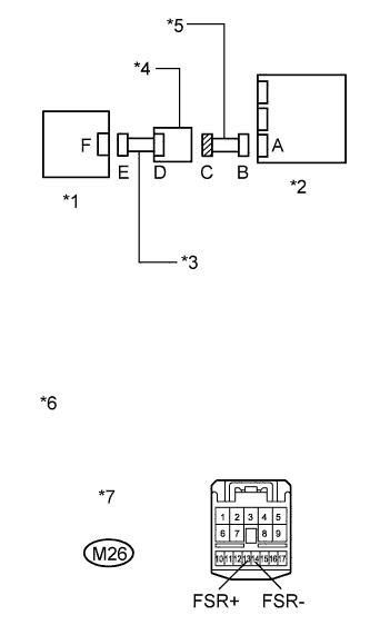
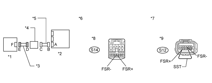
Text in Illustration *1 Occupant Classification ECU *2 Center Airbag Sensor Assembly *3 Front Seat Wire RH *4 Junction Connector *5 No. 2 Floor Wire *6 Front view of wire harness connector
(to Junction Connector)
*7 Connector C Turn the ignition switch off.
-
Disconnect the cable from the negative (-) battery terminal, and wait for at least 90 seconds.
-
Disconnect the junction connector from the No. 2 floor wire.
-
Connect the cable to the negative (-) battery terminal.
-
Turn the ignition switch to ON.
-
Measure the voltage according to the value(s) in the table below.
Standard Voltage Tester Connection Switch Condition Specified Condition M26-13 (FSR+) - Body ground Ignition switch ON Below 1 V M26-14 (FSR-) - Body ground Ignition switch ON Below 1 V
NG
REPLACE NO. 2 FLOOR WIRE
OK
-
-
CHECK FRONT SEAT WIRE RH (SHORT TO B+)
-
Text in Illustration *1 Occupant Classification ECU *2 Center Airbag Sensor Assembly *3 Front Seat Wire RH *4 Junction Connector *5 No. 2 Floor Wire *6 Front view of wire harness connector
(to Junction Connector)
*7 Connector D Turn the ignition switch off.
-
Disconnect the cable from the negative (-) battery terminal, and wait for at least 90 seconds.
-
Disconnect the front seat wire RH connector from the junction connector.
-
Connect the cable to the negative (-) battery terminal.
-
Turn the ignition switch to ON.
-
Measure the voltage according to the value(s) in the table below.
Standard Voltage Tester Connection Switch Condition Specified Condition S14-14 (FSR+) - Body ground Ignition switch ON Below 1 V S14-13 (FSR-) - Body ground Ignition switch ON Below 1 V
NG
REPLACE FRONT SEAT WIRE RH
OK
REPLACE JUNCTION CONNECTOR
-
-
CHECK NO. 2 FLOOR WIRE (OPEN)
-
Disconnect the junction connector from the No. 2 floor wire.
Tech Tips
SST has already been inserted into connector B.
-
Measure the resistance according to the value(s) in the table below.
Standard Resistance Tester Connection Condition Specified Condition M26-13 (FSR+) - M26-14 (FSR-) Always Below 1 Ω Text in Illustration *1 Occupant Classification ECU *2 Center Airbag Sensor Assembly *3 Front Seat Wire RH *4 Junction Connector *5 No. 2 Floor Wire *6 Front view of wire harness connector
(to Center Airbag Sensor Assembly)
*7 Front view of wire harness connector
(to Junction Connector)
*8 Connector B *9 Connector C - -
NG
REPLACE NO. 2 FLOOR WIRE
OK
-
-
CHECK FRONT SEAT WIRE RH (OPEN)
-
Disconnect the front seat wire RH connector from the junction connector.
-
Using SST, connect terminals 8 (FSR+) and 4 (FSR-) of connector E.
Note
Do not forcibly insert SST wire into the terminals of the connector when connecting.
-
Measure the resistance according to the value(s) in the table below.
Standard Resistance Tester Connection Condition Specified Condition S14-14 (FSR+) - S14-13 (FSR-) Always Below 1 Ω Text in Illustration *1 Occupant Classification ECU *2 Center Airbag Sensor Assembly *3 Front Seat Wire RH *4 Junction Connector *5 No. 2 Floor Wire *6 Front view of wire harness connector
(to Junction Connector)
*7 Front view of wire harness connector
(to Occupant Classification ECU)
*8 Connector D *9 Connector E - -
NG
REPLACE FRONT SEAT WIRE RH
OK
REPLACE JUNCTION CONNECTOR
-
-
CHECK NO. 2 FLOOR WIRE (SHORT)
-
Text in Illustration *1 Occupant Classification ECU *2 Center Airbag Sensor Assembly *3 Front Seat Wire RH *4 Junction Connector *5 No. 2 Floor Wire *6 Front view of wire harness connector
(to Junction Connector)
*7 Connector C Disconnect the junction connector from the No. 2 floor wire.
-
Measure the resistance according to the value(s) in the table below.
Standard Resistance Tester Connection Condition Specified Condition M26-13 (FSR+) - M26-14 (FSR-) Always 1 MΩ or higher
NG
REPLACE NO. 2 FLOOR WIRE
OK
-
-
CHECK FRONT SEAT WIRE RH (SHORT)
-
Text in Illustration *1 Occupant Classification ECU *2 Center Airbag Sensor Assembly *3 Front Seat Wire RH *4 Junction Connector *5 No. 2 Floor Wire *6 Front view of wire harness connector
(to Junction Connector)
*7 Connector D Disconnect the front seat wire RH connector from the junction connector.
-
Measure the resistance according to the value(s) in the table below.
Standard Resistance Tester Connection Condition Specified Condition S14-14 (FSR+) - S14-13 (FSR-) Always 1 MΩ or higher
NG
REPLACE FRONT SEAT WIRE RH
OK
REPLACE JUNCTION CONNECTOR
-
-
CHECK NO. 2 FLOOR WIRE (SHORT TO GROUND)
-
Text in Illustration *1 Occupant Classification ECU *2 Center Airbag Sensor Assembly *3 Front Seat Wire RH *4 Junction Connector *5 No. 2 Floor Wire *6 Front view of wire harness connector
(to Junction Connector)
*7 Connector C Disconnect the junction connector from the No. 2 floor wire.
-
Measure the resistance according to the value(s) in the table below.
Standard Resistance Tester Connection Condition Specified Condition M26-13 (FSR+) - Body ground Always 1 MΩ or higher M26-14 (FSR-) - Body ground Always 1 MΩ or higher
NG
REPLACE NO. 2 FLOOR WIRE
OK
-
-
CHECK FRONT SEAT WIRE RH (SHORT TO GROUND)
-
Text in Illustration *1 Occupant Classification ECU *2 Center Airbag Sensor Assembly *3 Front Seat Wire RH *4 Junction Connector *5 No. 2 Floor Wire *6 Front view of wire harness connector
(to Junction Connector)
*7 Connector D Disconnect the front seat wire RH connector from the junction connector.
-
Measure the resistance according to the value(s) in the table below.
Standard Resistance Tester Connection Condition Specified Condition S14-14 (FSR+) - Body ground Always 1 MΩ or higher S14-13 (FSR-) - Body ground Always 1 MΩ or higher
NG
REPLACE FRONT SEAT WIRE RH
OK
REPLACE JUNCTION CONNECTOR
-