CENTER AIRBAG SENSOR ASSEMBLY INSTALLATION

-
INSTALL CENTER AIRBAG SENSOR ASSEMBLY
-
Check that the ignition switch is off.
-
Check that the cable is disconnected from the negative (-) battery terminal.
CAUTION:
Wait at least 90 seconds after disconnecting the cable from the negative (-) battery terminal to disable the SRS system.
-
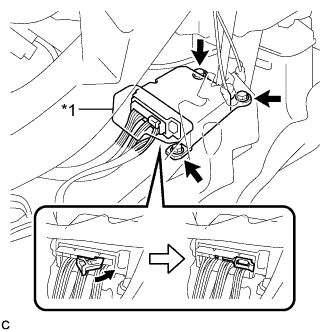
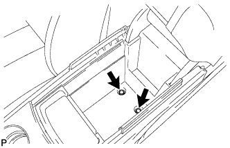
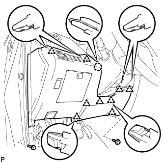
Text in Illustration *1 Waterproof Sheet Install the center airbag sensor assembly with the 3 bolts.
- Torque:
- 18 N*m { 178 kgf*cm, 13 ft.*lbf }
Note
-
If the center airbag sensor assembly has been dropped, or there are any cracks, dents or other defects in the case or connector, replace it with a new one.
-
When installing the center airbag sensor assembly, be careful that the SRS wiring does not interfere with or is not pinched between other parts.
-
When the ignition switch is first turned to on after the center airbag sensor assembly has been replaced, make sure that no one is in the vehicle.
-
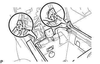
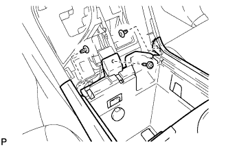
Connect the connector to the center airbag sensor assembly as shown in the illustration.
Note
When connecting the airbag connector, take care not to damage the airbag wire harness.
-
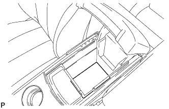
Check that the waterproof sheet is properly set.
-
Check that there is no looseness in the installation parts of the center airbag sensor assembly.
-
-
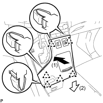
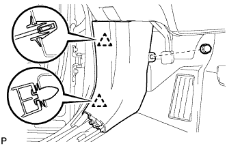
INSTALL CONSOLE BOX SUB-ASSEMBLY
-
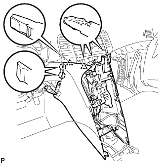
Engage the 2 claws and 4 clips.
-
Engage the 2 clamps.
-
Connect the connector.
-
Install the clip.
-
Install the console box sub-assembly with the 2 screws <E> or <F>.
-
-
INSTALL SHIFT LEVER KNOB SUB-ASSEMBLY
-
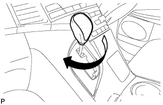
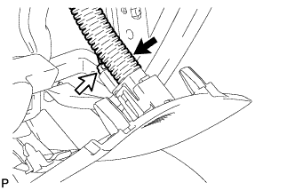
Turn the shift lever knob clockwise to install the shift lever knob sub-assembly.
-
-
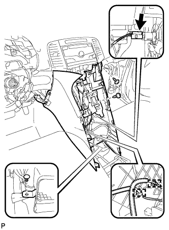
INSTALL CONSOLE BOX ASSEMBLY
-
Connect the connectors.
-
Engage the 2 claws.
-
Install the screw and 2 clips.
-
Install the console box assembly with the 2 bolts.
-
-
INSTALL NO. 2 CONSOLE BOX CARPET
-
Install the No. 2 console box carpet.
-
-
INSTALL LOWER INSTRUMENT PANEL SUB-ASSEMBLY
-
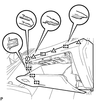
Connect the connectors.
-
Engage the 5 guides, 2 clips and claw.
-
Install the lower instrument panel sub-assembly with the bolt <C> and 4 screws <E> or <F>.
-
-
INSTALL NO. 2 INSTRUMENT PANEL UNDER COVER SUB-ASSEMBLY
-
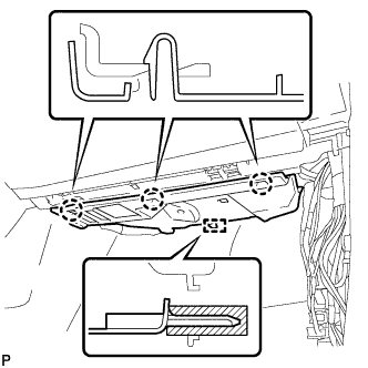
Engage the guide and 3 claws to install the No. 2 instrument panel under cover sub-assembly.
-
-
INSTALL COWL SIDE TRIM SUB-ASSEMBLY RH
Tech Tips
Use the same procedure as for the LH side Click here.
-
INSTALL FRONT DOOR SCUFF PLATE RH
Tech Tips
Use the same procedure as for the LH side Click here.
-
INSTALL AIR CONDITIONER CONTROL ASSEMBLY
-
Connect the connector.
-
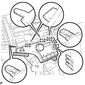
Engage the 2 clips and 4 guides.
-
Remove the protective tape.
Text in Illustration *1 Protective Tape -
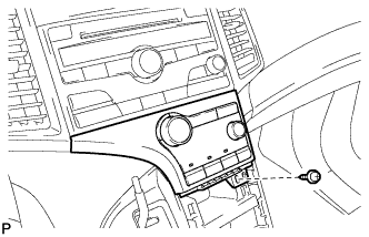
Install the air conditioning control assembly with the screw.
-
-
INSTALL UPPER CONSOLE PANEL SUB-ASSEMBLY
-
Connect the connectors.
-
Engage the 6 clips to install the upper console panel sub-assembly as shown in the illustration.
-
-
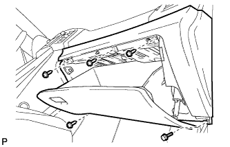
INSTALL LOWER NO. 1 INSTRUMENT PANEL FINISH PANEL
-
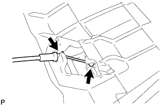
Connect the hood lock control cable.
-
Connect the aspirator duct and connector.
-
Connect the connectors.
-
Engage the claw and 9 clips.
-
Install the lower No. 1 instrument panel finish panel with the bolt <C> and screw <E> or <F>.
-
-
INSTALL COWL SIDE TRIM SUB-ASSEMBLY LH
-
Engage the 2 clips to install the cowl side trim sub-assembly LH.
-
Install the clip.
-
-
INSTALL FRONT DOOR SCUFF PLATE LH
-
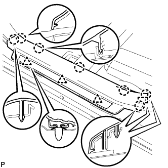
Engage the guide, 3 clips and the 7 claws to install the front door scuff plate LH.
-
-
CONNECT CABLE TO NEGATIVE BATTERY TERMINAL
Note
When disconnecting the cable, some systems need to be initialized after the cable is reconnected Click here.
-
PERFORM DIAGNOSTIC SYSTEM CHECK
-
Perform a diagnostic system check Click here.
-
-
INSPECT SRS WARNING LIGHT
-
Inspect the SRS warning light Click here.
-