METER / GAUGE SYSTEM Power Source Circuit
DESCRIPTION
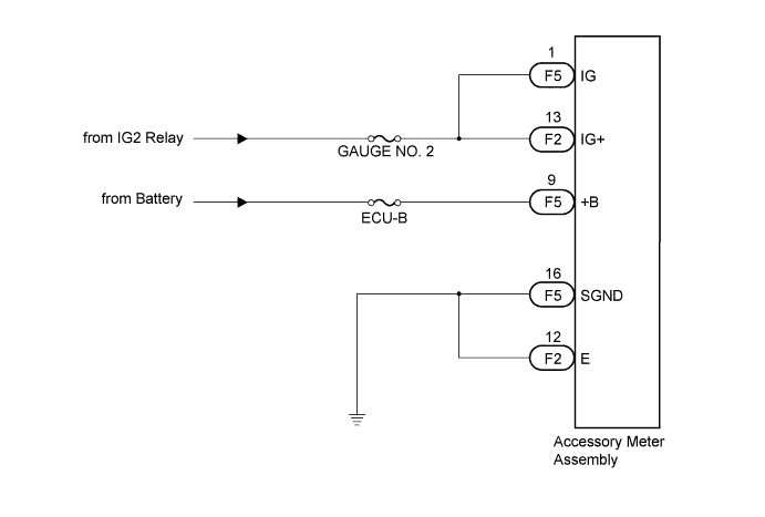
This circuit is the power source circuit for the accessory meter assembly. This circuit provides two types of power sources; one is a constant power source mainly used as a backup power source, and the other is a power source mainly used for signal transmission.
Tech Tips
If the accessory meter assembly displays "1:00" when the ignition switch is turned off, then to ON again, the +B terminal has a malfunction.
The maximum clock assembly margin of error is -4 to 4 seconds per day when the temperature is between -20°C (-4°F) and 60°C (140°F).
WIRING DIAGRAM
INSPECTION PROCEDURE
PROCEDURE
-
CHECK HARNESS AND CONNECTOR (ACCESSORY METER ASSEMBLY CIRCUIT)
-
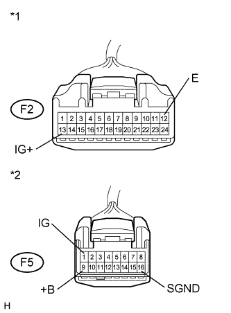
Text in Illustration *1 Front view of wire harness connector
(to Accessory Meter Assembly)
*2 Front view of wire harness connector
(to Accessory Meter Assembly )
Disconnect the F2 and F5 connectors.
-
Measure the voltage according to the value(s) in the table below.
Standard Voltage Tester Connection Condition Specified Condition F5-1 (IG) - Body ground Ignition switch ON 11 to 14 V F5-9 (+B) - Body ground Always 11 to 14 V F2-13 (IG+) - Body ground Ignition switch ON 11 to 14 V -
Measure the resistance according to the value(s) in the table below.
Standard Resistance Tester Connection Condition Specified Condition F2-12 (E) - Body ground Always Below 1 Ω F5-16 (SGND) - Body ground Always Below 1 Ω
NG 
REPAIR OR REPLACE HARNESS OR CONNECTOR
OK 
REPLACE ACCESSORY METER ASSEMBLY Click here
-