METER / GAUGE SYSTEM Clock Display Circuit
DESCRIPTION
The accessory meter assembly uses this circuit to communicate with the combination meter assembly via the direct line. The accessory meter assembly uses this circuit to receive the drive monitor switch signals from the combination meter assembly via the direct line and multi-information display signal from each ECU through the combination meter assembly via the direct line.
Tech Tips
Each ECU outputs the DTCs when each system has a malfunction.
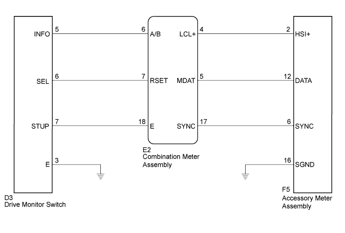
WIRING DIAGRAM
INSPECTION PROCEDURE
PROCEDURE
-
SYSTEM CHECK
-
Confirm the symptom.
Result Result Proceed to Clock display does not indicate cruise information display (The display only illuminates). A Multi-information display does not change when the drive monitor switch is operated. B
B 
CHECK HARNESS AND CONNECTOR (COMBINATION METER ASSEMBLY - DRIVE MONITOR SWITCH) Click here
A 
-
-
CHECK CAN COMMUNICATION SYSTEM
-
Check if a CAN communication DTC is output Click here.
Result Result Proceed to CAN communication DTC is not output. A CAN communication DTC is output. B
B 
GO TO CAN COMMUNICATION SYSTEM Click here
A
-
-
CHECK HARNESS AND CONNECTOR (ACCESSORY METER ASSEMBLY - COMBINATION METER ASSEMBLY)
-
Disconnect the E2 and F5 connectors.
-
Measure the resistance according to the value(s) in the table below.
Standard Resistance Tester Connection Condition Specified Condition F5-2 (HSI+) - E2-4 (LCL+) Always Below 1 Ω F5-12 (DATA) - E2-5 (MDAT) Always Below 1 Ω F5-6 (SYNC) - E2-17 (SYNC) Always Below 1 Ω E2-4 (LCL+) - Body ground Always 10 kΩ or higher E2-5 (MDAT) - Body ground Always 10 kΩ or higher E2-17 (SYNC) - Body ground Always 10 kΩ or higher F5-16 (SGND) - Body ground Always Below 1 Ω
NG
REPAIR OR REPLACE HARNESS OR CONNECTOR
OK
-
-
INSPECT COMBINATION METER ASSEMBLY
-
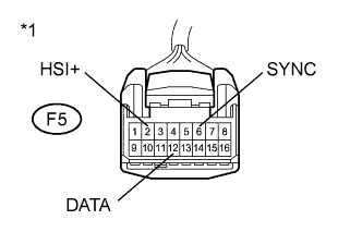
Text in Illustration *1 Front view of wire harness connector
(to Accessory Meter Assembly)
Reconnect the E2 connector.
-
Connect an oscilloscope to the accessory meter assembly connector.
-
Check for pulses.
Standard Tester Connection Condition Specified Condition F5-2 (HSI+) - Body ground Ignition switch ON Pulse generation F5-12 (DATA) - Body ground Ignition switch ON Pulse generation F5-6 (SYNC) - Body ground Ignition switch ON Pulse generation
NG
REPLACE COMBINATION METER ASSEMBLY Click here
OK 
REPLACE ACCESSORY METER ASSEMBLY Click here
-
-
CHECK HARNESS AND CONNECTOR (COMBINATION METER ASSEMBLY - DRIVE MONITOR SWITCH)
-
Disconnect the E2 and D3 connectors.
-
Measure the resistance according to the value(s) in the table below.
Standard Resistance Tester Connection Condition Specified Condition E2-6 (A/B) - D3-5 (INFO) Always Below 1 Ω E2-6 (A/B)- Body ground Always 10 kΩ or higher E2-7 (RSET) - D3-6 (SEL) Always Below 1 Ω E2-7 (RSET) - Body ground Always 10 kΩ or higher E2-18 (E) - D3-7 (STUP) Always Below 1 Ω E2-18 (E)- Body ground Always 10 kΩ or higher D3-3 (E) - Body ground Always Below 1 Ω
NG
REPAIR OR REPLACE HARNESS OR CONNECTOR
OK
-
-
INSPECT DRIVE MONITOR SWITCH
-
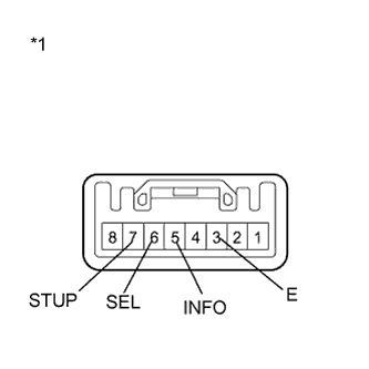
Text in Illustration *1 Component without harness connected
(Drive Monitor Switch)
Disconnect the D3 connector.
-
Measure the resistance according to the value(s) in the table below.
Standard Resistance Tester Connection Condition Specified Condition 3 (E) - 5 (INFO) Ignition switch ON and INFO switch pressed Below 1 Ω Ignition switch ON and INFO switch released 10 kΩ or higher 3 (E) - 6 (SEL) Ignition switch ON and SELECT RESET switch pressed Below 1 Ω Ignition switch ON and SELECT RESET switch released 10 kΩ or higher 3 (E) - 7 (STUP) Ignition switch ON and SETUP switch pressed Below 1 Ω Ignition switch ON and SETUP switch released 10 kΩ or higher
NG
REPLACE DRIVE MONITOR SWITCH Click here
OK
REPLACE COMBINATION METER ASSEMBLY Click here
-