METER / GAUGE SYSTEM Meter Illumination is Always Dark
DESCRIPTION
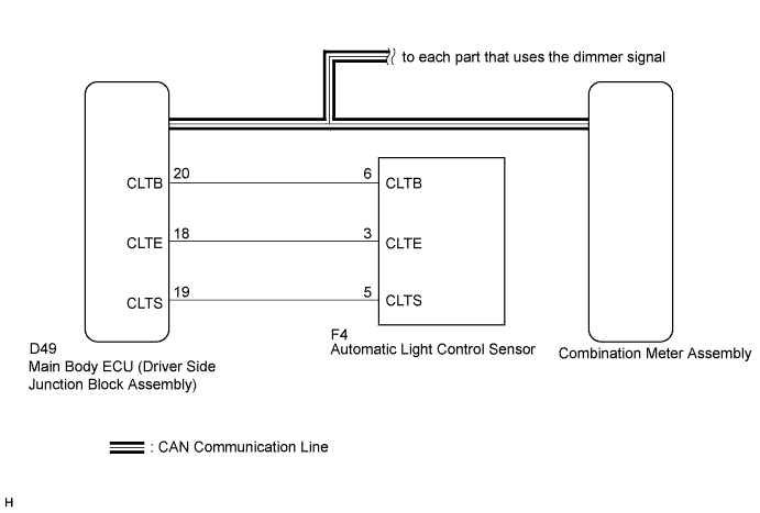
In this circuit, the meter CPU receives auto dimmer signals from the main body ECU (driver side junction block assembly) using the CAN communication system. When the meter CPU receives an auto dimmer signal, it dims the meter illumination (warning and indicator lights). The main body ECU (driver side junction block assembly) determines whether it is daytime, twilight, or nighttime based on the waveform transmitted from the automatic light control sensor. If the main body ECU (driver side junction block assembly) determines that it is daytime, the ECU does not send an auto dimmer signal. Therefore, the meter illumination will not dim even if the driver accidentally turns the light control switch to the tail or head position in daytime.
Tech Tips
When the meter illumination is always dark, there may be a malfunction in the automatic light control sensor, main body ECU (driver side junction block assembly), CAN communication system, harness or connector, or combination meter assembly.
WIRING DIAGRAM
INSPECTION PROCEDURE
Tech Tips
-
The meter illumination can be customized by turning the light control rheostat knob in the combination meter assembly.
-
If the light control rheostat knob is turned fully clockwise and the light control switch is turned to the tail, head, or AUTO position at night, the meter illumination goes off.
PROCEDURE
-
CHECK CAN COMMUNICATION SYSTEM
-
Check if a CAN communication DTC is output Click here.
Result Result Proceed to CAN communication DTC is not output. A CAN communication DTC is output. B
B 
GO TO CAN COMMUNICATION SYSTEM Click here
A 
-
-
CHECK DTC (LIGHT SENSOR CIRCUIT)
-
Check if DTC B1244 is output Click here.
Result Result Proceed to B1244 is not output. A B1244 is output. B
B
GO TO LIGHTING SYSTEM Click here
A
-
-
CHECK OPERATION (ACCESSORY METER ASSEMBLY)
-
Turn the ignition switch to ON.
-
Turn the light control switch to the tail, head, or AUTO position.
-
Cover the automatic light control sensor.
-
Check the accessory meter assembly illumination.
Result Result Proceed to Accessory meter assembly illumination does not operate normally. A Accessory meter assembly illumination operates normally. B Tech Tips
The accessory meter assembly illumination dims according to the dimmer signal as the combination meter assembly does. Therefore, when only the meter illumination is always dark, there may be a malfunction in the combination meter assembly.
B
REPLACE COMBINATION METER ASSEMBLY Click here
A
-
-
CHECK OPERATION (AUTOMATIC LIGHT CONTROL SYSTEM)
-
Turn the ignition switch to ON.
-
Turn the light control switch to the AUTO position.
-
Cover the automatic light control sensor.
-
Check the taillights and low beam headlights.
OK The taillights and low beam headlights come on. -
Uncover the automatic light control sensor.
-
Check the low beam headlights and taillights.
OK The low beam headlights and taillights go off. Result Result Proceed to Automatic light control system operates normally. A Automatic light control system does not operate normally. B
B
CHECK LIGHTING SETTING Click here
A
-
-
REPLACE MAIN BODY ECU (DRIVER SIDE JUNCTION BLOCK ASSEMBLY)
-
Replace the main body ECU (driver side junction block assembly) with a new or a normal one Click here.
OK The operation of the combination meter assembly returns to normal. Tech Tips
The meter CPU controls the meter illumination based on an auto dimmer signal from the main body ECU (driver side junction block assembly). When the meter illumination is always dark (very dim), it may be due to the main body ECU (driver side junction block assembly) sending an auto dimmer signal to the meter CPU because of a malfunction in the main body ECU (driver side junction block assembly).
NG
REPLACE COMBINATION METER ASSEMBLY Click here
OK 
END
-