METER / GAUGE SYSTEM SYSTEM DESCRIPTION

-
OUTLINE OF THE COMBINATION METER ASSEMBLY
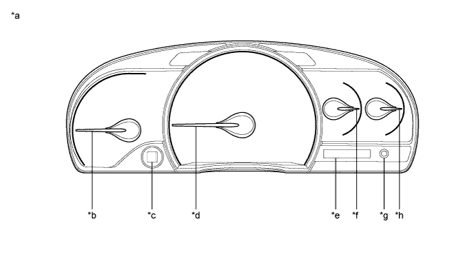
Text in Illustration *a Indication Example *b Tachometer *c A/T Shift Indicator *d Speedometer *e ODO/TRIP Meter *f Fuel Receiver Gauge *g Light Control Rheostat Knob *h Engine Coolant Temperature Receiver Gauge
-
Meter or Gauge
Item Detail Speedometer Indicates the vehicle speed based on a signal received from the skid control ECU. Tachometer Indicates the engine speed based on a signal received from the ECM. Fuel Receiver Gauge Indicates the fuel level based on a signal received from the fuel sender gauge assembly. Engine Coolant Temperature Receiver Gauge Indicates the engine coolant temperature based on a signal received from the ECM. -
Warning, Indicator, or Reminder
Item Detail Beam Receives a beam indicator light signal from the main body ECU (driver side junction block assembly). Turn Receives a turn signal from the turn signal flasher. Fuel Receives a fuel signal from the fuel sender gauge. Brake Receives a brake signal from the brake fluid level warning switch and the skid control ECU. SRS Receives an SRS signal from the center airbag sensor assembly. Open door Receives a door condition signal from the main body ECU (driver side junction block assembly). Oil pressure Receives an oil pressure warning light signal from the oil pressure switch. Charge Receives a charge indicator light signal from the generator. MIL (Check engine warning light) Receives a MIL (check engine warning light) signal from the ECM. Driver side seat belt Receives a driver side seat belt signal from the main body ECU (driver side junction block assembly). ABS Receives an ABS signal from the skid control ECU. EPS Receives an EPS signal from the power steering ECU. Front fog Receives a front fog indicator light signal from the main body ECU (driver side junction block assembly). Rear fog Receives a rear fog indicator light signal from the main body ECU (driver side junction block assembly). Headlight leveling Receives a headlight leveling signal from the headlight leveling ECU assembly. Automatic high beam*1 Receives an automatic high beam signal from the main body ECU (driver side junction block assembly). Tail Receives a tail signal from the main body ECU (driver side junction block assembly). Cruise SET Receives a cruise SET signal from the ECM. AWD*2 Receives an AWD signal from the AWD control ECU. VSC OFF indicator light Receives a VSC OFF signal from the skid control ECU. TRC OFF indicator light Receives a TRC OFF signal from the skid control ECU. Security Receives a security indicator light signal from the certification ECU (smart key ECU assembly)*3 or transponder key ECU assembly*4. Front passenger side airbag ON/OFF Receives a front passenger side airbag ON/OFF signal from the center airbag sensor assembly. Master warning Comes on when the reminder message or warning message appears on the multi-information display. Slip Receives a slip signal from the skid control ECU. Cruise Receives a cruise signal from the ECM. Front passenger side seat belt Receives a front passenger side seat belt buckle switch signal from the center airbag sensor assembly and transmits a front passenger side seat belt warning light signal to the accessory meter assembly. A/T shift Receives an A/T shift condition signal from the park/neutral position switch*4 and the ECM.
-
*1: w/ Automatic High Beam System
-
*2: for AWD
-
*3: w/ Smart Entry and Start System
-
*4: w/o Smart Entry and Start System
-
-
-
ACCESSORY METER ASSEMBLY
Item Detail Cruise information display Average fuel consumption Six types of information (average fuel consumption, average vehicle speed, driving time, current fuel consumption, and driving range) can be displayed. Average vehicle speed Driving time Current fuel consumption Driving range Multi-information display Each system warning Interrupts the multi-information display immediately when a warning occurs. DTC (Diagnostic Trouble Code) display Displays 2 digit DTCs pertaining to the VSC function. Custom setting display Displays the customized setting of each item. Outside temperature Displays the outside temperature. Illumination control Displays the current illumination level and adjust the combination meter assembly brightness. ODO/TRIP meter Indicates the driving distance. -
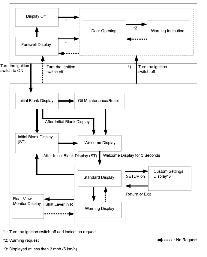
MULTI-INFORMATION DISPLAY FLOW CHART
-
Multi-information Display Flow Chart
-
-
DIAGNOSIS SYSTEM
Tech Tips
-
The multi-information display shows "DIAG" when turn the ignition switch to ON Click here.
-
Diagnosis information can be displayed on the multi-information display after connecting a jumper wire between terminals TC and CG of the DLC3 connector.
-
-
LED INITIAL CHECK
-
Check the illumination function of the warning, indicator, or reminder light listed below when turn the ignition switch to ON.
-
*1: for AWD
-
-